
A cutting device for new material production

A cutting device and new material technology, applied in plastic recycling, recycling technology, metal processing, etc., can solve the problems of low efficiency and high labor cost

Active Publication Date: 2022-06-07
胡媛媛
View PDF17 Cites 0 Cited by
  • Summary
  • Abstract
  • Description
  • Claims
  • Application Information

AI Technical Summary

Problems solved by technology

[0005] In order to overcome the shortcomings of the traditional cutting method, which is that workers hold cutting tools to cut, the labor cost is high and the efficiency is low, the technical problem is: to provide a cutting device for new material production that automatically cuts off new materials, automatically transports and automatically cuts off materials at intervals

Method used


Image

  • A cutting device for new material production
  • A cutting device for new material production
  • A cutting device for new material production

Examples


Embodiment 1

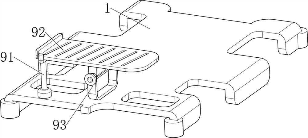
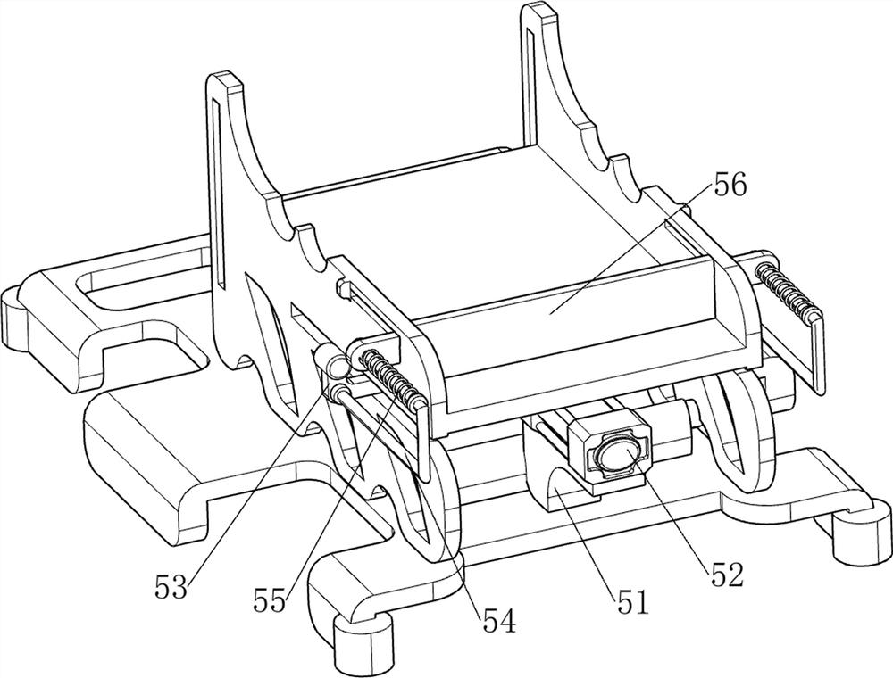
[0059] A cutting device for the production of new materials, such as Figure 1-3 As shown, it includes a base frame 1, a first support frame 2, a first cutter 3, a second cutter 4, a pushing mechanism 5 and a cutting mechanism 6, the base frame 1 is provided with a first support frame 2, the base frame 1 and A pushing mechanism 5 is connected between the first support frame 2, a cutting mechanism 6 is connected between the bottom frame 1 and the front part of the first support frame 2, and the upper and lower sides of the cutting mechanism 6 are slidably installed with a first knife 3 and a second cutting mechanism. The two cutters 4 , the first cutter 3 and the second cutter 4 are all slidably connected with the first support frame 2 .

[0060] The worker first puts the new material on the first support frame 2, starts the operation of the pusher mechanism 5, the pusher mechanism 5 will push the new material to the bottom of the second cutter 4, the worker slides the cutting ...

Embodiment 2

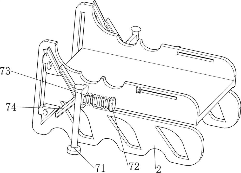
[0066] On the basis of Example 1, as Figure 4-7 As shown, it also includes a pressing mechanism 7, and the pressing mechanism 7 also includes a first sliding sleeve 71, a second sliding rod 72, a third spring 73 and a pressing rod 74, and the left and right sides of the upper middle of the first support frame 2 Both are provided with a first sliding sleeve 71 , a second sliding rod 72 is slidably provided on the two first sliding sleeves 71 , and a third spring 73 is wound around the second sliding rod 72 , and the third spring 73 is connected to the first sliding rod 72 . Between the sleeve 71 and the second sliding rod 72 , the front parts of the two first sliding sleeves 71 are provided with extrusion rods 74 , and the two first wedge blocks 63 on the same side are matched with the extrusion rods 74 on the same side.

[0067] When the first push frame 53 moves forward, the first push frame 53 moves forward to drive the second sliding rod 72 to move forward, and the third s...


PUM


Abstract

The invention relates to a cutting device, in particular to a cutting device for new material production. The invention provides a cutting device for new material production which automatically cuts new materials, automatically transports and automatically cuts materials at intervals. A cutting device for new material production, comprising: a bottom frame and a first support frame, the bottom frame is provided with a first support frame, and a pushing mechanism is connected between the bottom frame and the first support frame; a cutting mechanism, the bottom frame A cutting mechanism is connected between the first support frame; the first cutter and the second cutter, the first cutter and the second cutter are slidably installed on the upper and lower sides of the cutting mechanism, and the first cutter and the second cutter are connected to the first support rack slide connection. The present invention is equipped with a pushing mechanism, and the pushing mechanism cooperates with the cutting mechanism to transport new materials and cut off the new materials at the same time; through the cooperation of the pushing mechanism and the automatic cutting mechanism, the cutting of new materials can be realized Work.

Description

technical field [0001] The invention relates to a cutting device, in particular to a cutting device for the production of new materials. Background technique [0002] The output value of the world material industry is growing at a rate of about 30% every year. For example, new chemical materials, microelectronics, optoelectronics, and new energy have become the most active, fastest-growing and most promising new material fields for investors. Material innovation has become One of the important driving forces to promote the progress of human civilization has also promoted the development of technology and the upgrading of industries. One of the main directions of scientific and technological development in the 21st century is the development and application of new materials. In the process of production and processing of new materials, cutting them is one of the processes. The traditional cutting method is that workers hold cutting tools to cut, which has high labor costs and...

Claims


Application Information

Patent Timeline
Patent Type & Authority Patents(China)
IPC IPC(8): B23D79/00B23Q7/00B23Q7/06
CPCB23D79/00B23Q7/00B23Q7/06Y02W30/62
Inventor 胡媛媛
Owner 胡媛媛
Learn More