Laser welding jig

A laser welding and jig technology, which is applied in laser welding equipment, welding equipment, welding equipment, etc., can solve the problems of potential safety hazards, uneven glass lamination, and difficult uniform clamping force of jigs, etc., so as to facilitate welding Uniform operation, clamping force, uniform fit effect

Pending Publication Date: 2021-10-22
崔晓晓
View PDF0 Cites 0 Cited by
  • Summary
  • Abstract
  • Description
  • Claims
  • Application Information

AI Technical Summary

Problems solved by technology

The clamping force of the existing fixtures is difficult to ensure uniformity, and there is a problem of uneven bonding between the glasses welded by the fixtures, which poses a safety hazard

Method used


Image

  • Laser welding jig
  • Laser welding jig

Examples


Embodiment Construction

[0042] The present invention is described in detail below in conjunction with accompanying drawing:

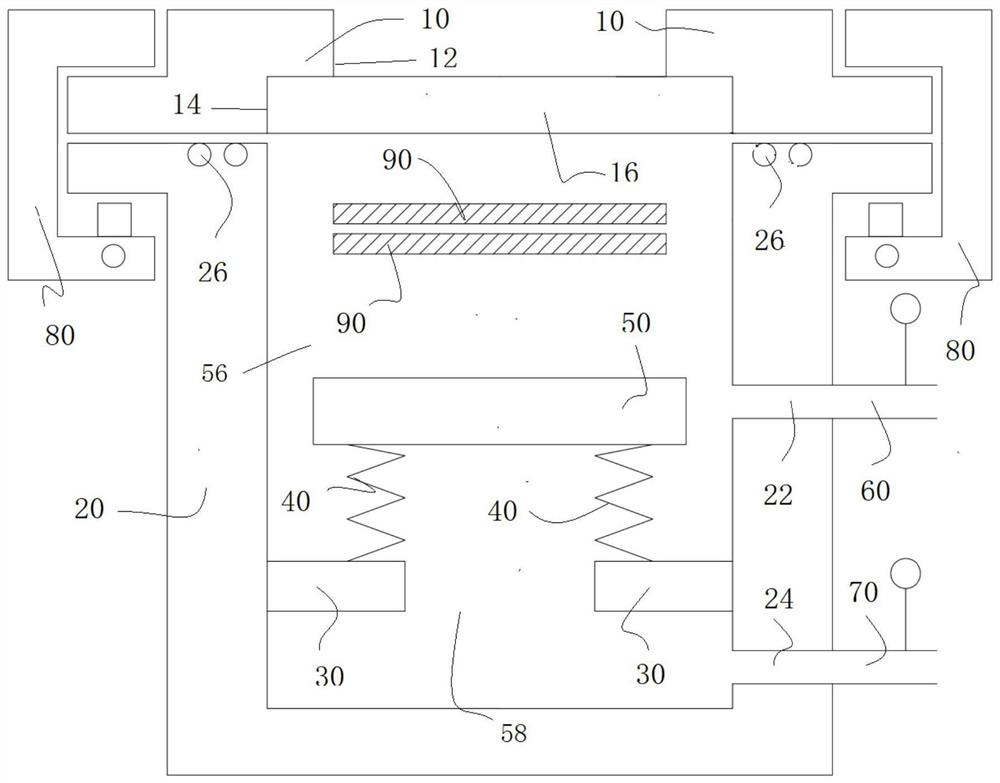
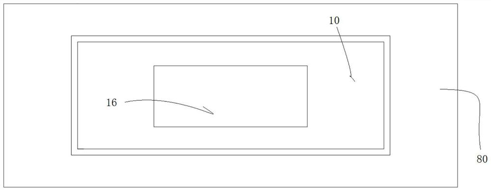
[0043] According to an embodiment of the present invention, a laser welding jig is provided. see figure 1 and figure 2 , the laser welding jig includes a lower casing 20 , an upper cover 10 , a support member 30 , an elastic member 40 and a bearing member 50 . Wherein, the upper cover 10 is provided with a transparent window 16 . The upper cover 10 is detachably connected to the lower case 20 . The upper cover 10 can be connected with the lower casing 20, or can be disassembled and separated.

[0044] The supporting member 30 is fixedly connected to the inner wall of the sealed cavity, and is used for supporting the connecting elastic member 40 . One end of the elastic member 40 is connected to the supporting member 30 . The bearing member 50 is connected to the other end of the elastic member 40 and can be used to place the workpiece 90 to be welded. The elastic membe...


PUM


Abstract

The invention provides a laser welding jig. The laser welding jig comprises a lower shell, an upper cover, a supporting piece, an elastic piece and a bearing piece; the upper cover is detachably connected to the lower shell, and a sealing cavity is defined by the upper cover and the lower shell; a transparent window is arranged on the upper cover; the supporting piece is fixedly connected to the inner wall of the sealing cavity; one end of the elastic piece is connected to the supporting piece; the bearing piece is connected to the other end of the elastic piece and used for placing a workpiece to be welded; the supporting piece, the elastic piece and the bearing piece divide the sealing cavity into a first cavity and a second cavity; the air pressure in the first cavity and / or the second cavity can be adjusted and is used for enabling the elastic piece to elastically deform, so that the bearing piece is driven to move towards the transparent window to a first position so as to clamp the workpiece to be welded between the bearing piece and the transparent window, or the bearing piece is driven to move back to the transparent window.

Description

technical field [0001] The invention relates to a laser welding jig. Background technique [0002] Laser welding technology has a relatively good welding level in material welding. As a transparent and brittle material, glass cannot be easily absorbed by traditional laser light sources, and glass is easily broken during welding due to its large thermal expansion coefficient, so it is not suitable for traditional laser welding. Therefore, it is necessary to use a special welding light source for welding, and use a high-power-density infrared femtosecond laser to generate nonlinear absorption between transparent materials to form effective solder joints. [0003] Existing jigs for laser welding glass rely on bolt fastening, pistons, cylinders and other mechanical movements to clamp and fit the glass to be welded, which is inefficient. Existing fixtures are not suitable for large-scale, large-scale glass welding. The clamping force of the existing jig is difficult to ensure ...

Claims


Application Information

Patent Timeline
IPC IPC(8): B23K26/70B23K37/04B23K26/21
CPCB23K26/702B23K37/0435B23K26/21
Inventor 崔晓晓
Owner 崔晓晓
Why Eureka
Try Eureka