
Clamping device for automatic helmet drilling machine

A technology of clamping device and drilling machine, which is applied in the direction of clamping device, positioning device, clamping, etc., can solve the problems of clamp clamping difficulty, helmet processing position deviation, and many scrapped products, so as to ensure the convenience of use, The effect of guaranteeing precision and ensuring accuracy

Inactive Publication Date: 2021-10-22
天津罗帝亚体育用品有限公司
View PDF8 Cites 4 Cited by
  • Summary
  • Abstract
  • Description
  • Claims
  • Application Information

AI Technical Summary

Problems solved by technology

The picture is a schematic diagram of the structure of an existing helmet finished product and blank. There are irregular surplus materials in the lower part of the helmet blank. Since holes need to be drilled on the main body of the helmet, only the lower part of the helmet can be clamped. The remaining material of the blank causes great difficulties in the clamping of the fixture
The existing fixture is difficult to accurately clamp the blank of the helmet, which often causes deviations in the processing position of the helmet, and the helmet automatic drilling machine cannot automatically identify and adjust, resulting in deviation of the hole position after drilling. As a result, accessories cannot be installed, resulting in more scrap products and seriously affecting production

Method used


Image

  • Clamping device for automatic helmet drilling machine
  • Clamping device for automatic helmet drilling machine
  • Clamping device for automatic helmet drilling machine

Examples


Embodiment Construction

[0031] The present invention will be clearly and completely described below in conjunction with the embodiments.

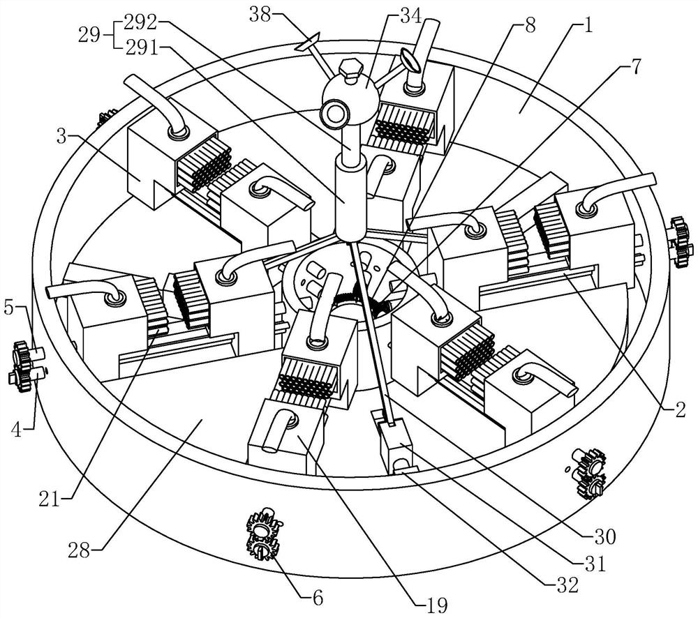
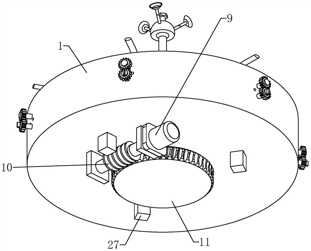
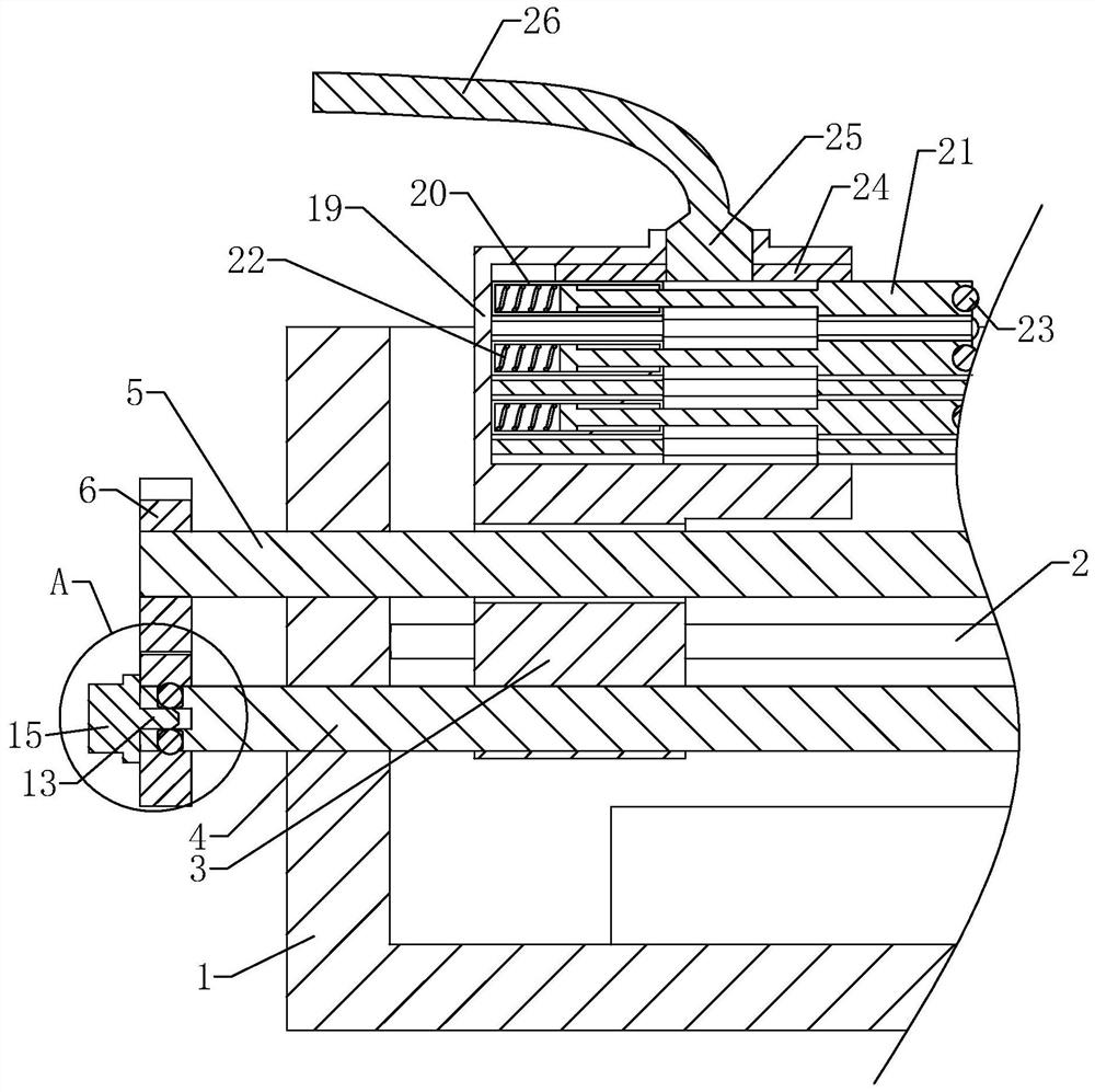
[0032] See attached figure 1 , a clamping device for an automatic helmet drilling machine, including a workbench 1, the workbench 1 is a disc-shaped structure, and the workbench 1 is installed on the helmet automatic drilling machine when practical. There are six radial clamping mechanisms on the workbench 1. The clamping mechanism includes two cylindrical rod-shaped slide rails 2 fixed on the workbench 1. Two slide seats 3 are provided for sliding on the slide rails 2. The clamping mechanism also includes a first threaded rod 4 and a second threaded rod 5 that are rotatably engaged with the workbench 1. The first threaded rod 4 and the second threaded rod 5 are threadedly engaged with the two sliding seats 3 respectively. The ends of the rod 4 and the second threaded rod 5 away from the axis of the workbench 1 are both provided with transmission gears 6 that mes...


PUM


Abstract

The invention discloses a clamping device for an automatic helmet drilling machine, and relates to the technical field of helmet machining equipment. The clamping device comprises a workbench, the workbench is of a circular structure, and a plurality of radial clamping mechanisms are arranged on the workbench; each clamping mechanism comprises a sliding rail fixed to the workbench, and two sliding seats are arranged on the sliding rails in a sliding mode; flexible clamps are arranged on the sliding seats; the clamping mechanism further comprises a first threaded rod and a second threaded rod which are rotatably matched with the workbench; the first threaded rod and the second threaded rod are in threaded fit with the two sliding seats correspondingly; transmission gears meshed with each other are arranged at the ends, away from the axis of the workbench, of the first threaded rod and the second threaded rod correspondingly; and a driven bevel gear is arranged at the end, close to the axis of the workbench, of the first threaded rod. The clamping device for the automatic helmet drilling machine provided by the invention is high in clamping precision and convenient to use.

Description

technical field [0001] The invention relates to the technical field of helmet processing equipment, in particular to a clamping device for a helmet automatic drilling machine. Background technique [0002] The racing helmet is a kind of sports protective gear that protects the athlete's head from injury in motorsports. The racing helmet is composed of the main body of the helmet, the goggles on the helmet, the inner lining of the helmet and other accessories. These accessories are installed on the helmet. When putting it on, you first need to drill holes in the helmet body, and then you can install accessories. [0003] The structure of the existing helmet automatic drilling machine is similar to the structure of a five-axis milling machine whose publication number is CN104668637A. The five-axis milling machine includes a base, a sliding table and a workpiece table. Three first slide rails are arranged in parallel in the lateral direction, and the slide table is slidably ar...

Claims


Application Information

Patent Timeline
Patent Type & Authority Applications(China)
IPC IPC(8): B23Q3/06B23Q3/08
CPCB23Q3/062B23Q3/08B23Q2703/04
Inventor 谢月光
Owner 天津罗帝亚体育用品有限公司
Learn More