
Electrically-driven hot-melting ruling machine

A marking machine and electric drive technology, applied in mechanical equipment, transmission devices, roads, etc., can solve the problems of equipment personnel injury, no braking function, small torque, etc.

Pending Publication Date: 2021-10-22
厦门绩程交通设施有限公司
View PDF0 Cites 0 Cited by
  • Summary
  • Abstract
  • Description
  • Claims
  • Application Information

AI Technical Summary

Problems solved by technology

[0003] The traditional hot-melt scribing machines are all carried out by hand push. This method is easy to operate and adaptable, but the work efficiency is low and the work intensity of the workers is high.
[0004] And some electric-driven hot-melt marking machines only have simple electric drive function, the torque is small, the operation is not flexible, and the motor is easy to be damaged when climbing; at the same time, it does not have the brake function, and it is easy to rush down directly when working downhill, which is harmful to the equipment. or personal injury

Method used


Image

  • Electrically-driven hot-melting ruling machine
  • Electrically-driven hot-melting ruling machine
  • Electrically-driven hot-melting ruling machine

Examples


Embodiment Construction

[0038] The present invention will be further described below in conjunction with the accompanying drawings. It should be noted that this embodiment is based on the technical solution, and provides detailed implementation and specific operation process, but the protection scope of the present invention is not limited to the present invention. Example.

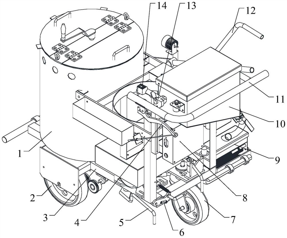
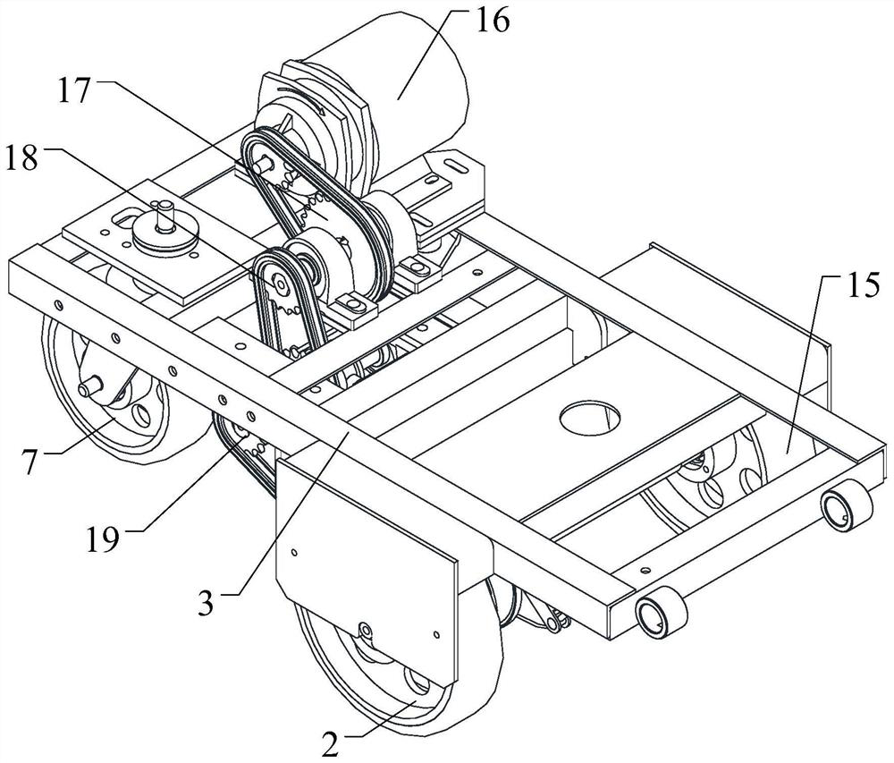
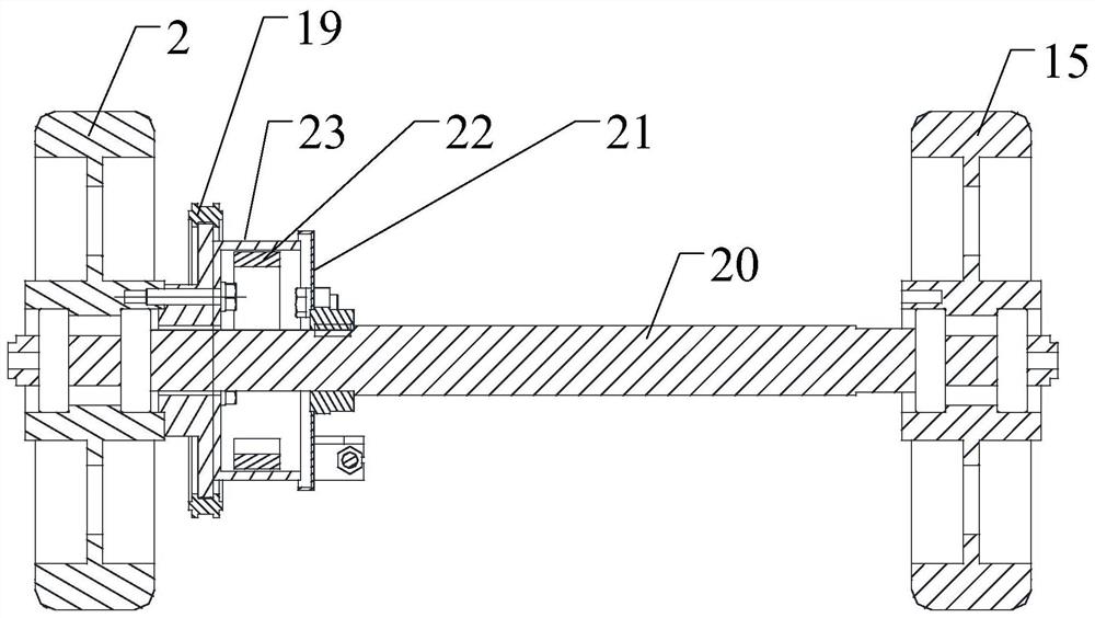
[0039] figure 1 It is a schematic diagram of the overall structure of an electric-driven hot-melt scribing machine according to an embodiment of the present invention; figure 2 It is a structural schematic diagram of a deceleration mechanism of an electric-driven hot-melt scribing machine according to an embodiment of the present invention; image 3 It is a transverse cross-sectional view of a braking mechanism of an electrically driven hot-melt scribing machine according to an embodiment of the present invention; Figure 4 It is an appearance diagram of a brake mechanism of an electric-driven hot-melt scribing machine accord...


PUM


Abstract

The invention discloses an electrically-driven hot-melting ruling machine which comprises a chassis assembly, a material barrel and a bead scattering device, wherein the material barrel and the bead scattering device are sequentially arranged at the top end of the chassis assembly from front to back, a glass bead box is arranged above the bead scattering device, a coating hopper assembly is arranged on one side of the material barrel, the chassis assembly comprises a chassis, a walking mechanism arranged at the bottom end of the chassis, a speed reducing mechanism and a brake mechanism, the speed reducing mechanism and the brake mechanism are connected with the walking mechanism, and the speed reducing mechanism is further connected with a driving motor and a clutch mechanism which are fixed to the top end of the chassis. According to the electrically-driven hot-melting ruling machine adopting the structure, the speed reducing mechanism and the brake mechanism are arranged, so that safe operation in the uphill and downhill processes is facilitated.

Description

technical field [0001] The invention relates to a hot-melt scribing machine technology, in particular to an electric-driven hot-melt scribing machine. Background technique [0002] In the process of highway construction, road marking is the basic work, and it is also the lifeline related to driving safety. In the prior art, a hot-melt marking machine is generally used for marking, and the powdery hot-melt paint melted at a high temperature of 200° is applied to the road surface by scraping. [0003] The traditional hot-melt scribing machines are all carried out by hand push. This method is easy to operate and adaptable, but the work efficiency is low and the work intensity of the workers is high. [0004] And some electric-driven hot-melt marking machines only have simple electric drive function, the torque is small, the operation is not flexible, and the motor is easy to be damaged when climbing; at the same time, it does not have the brake function, and it is easy to rush...

Claims


Application Information

Patent Timeline
IPC IPC(8): E01C23/20F16H7/06
CPCE01C23/20E01C23/203F16H7/06
Inventor 李华伟
Owner 厦门绩程交通设施有限公司
Learn More