Exhaust system mixer

An exhaust system and mixer technology, applied in the direction of exhaust devices, machines/engines, mechanical equipment, etc., can solve the problems of reducing the overall flow rate of the gas, reducing the exhaust effect of the exhaust system, and different, so as to improve the flow speed, The effect of improving the use value

Active Publication Date: 2021-10-22
东风佛吉亚排气控制技术有限公司
View PDF2 Cites 1 Cited by
  • Summary
  • Abstract
  • Description
  • Claims
  • Application Information

AI Technical Summary

Problems solved by technology

[0003] During the use of the existing exhaust system mixer, the internal structure of the mixer is square. When the gas passes through the square mixer, the pressure on each space point is different because the gas has not been evenly divided, and the pressure between the gases The resistance is large, so that the gas located at both ends of the mixer will have an impact in the horizontal direction during the circulation process, resulting in a decrease in the overall flow rate of the gas and reducing the exhaust effect of the exhaust system

Method used


Image

  • Exhaust system mixer
  • Exhaust system mixer
  • Exhaust system mixer

Examples


Embodiment 1

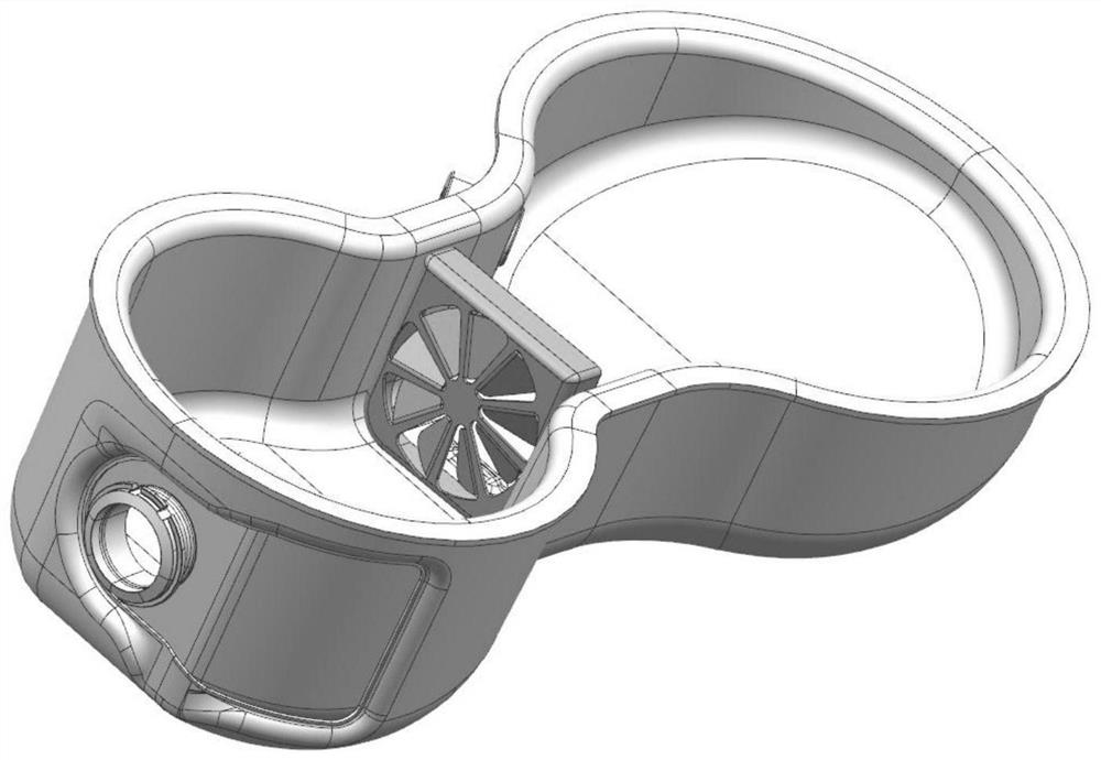
[0030] Such as figure 1 As shown, the exhaust system mixer of the present invention includes a casing 1, and the inner walls of both sides of the casing 1 in the middle are fixedly connected with the same mounting bracket 9, and the inner wall of the mounting frame 9 is fixedly connected with a fan-shaped mixer body 4, and the mounting frame 9 The outer wall close to the fan-shaped mixer body 4 is fixedly connected with the flow limiting frame 10, the outer wall of one side of the shell 1 is provided with an air intake hole, and the inner wall of the air intake hole is fixedly connected with the air intake pipe 2, and the outer wall of the other side of the shell 1 is opened with a exhaust hole, and the inner wall of the exhaust hole is fixedly connected with an exhaust pipe 6.

[0031] In this embodiment, the fan-shaped mixer body 4 is used to replace the square mixer, and the gas entering the housing 1 through the air inlet pipe 2 enters the other side of the mounting frame ...

Embodiment 2

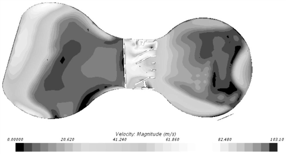
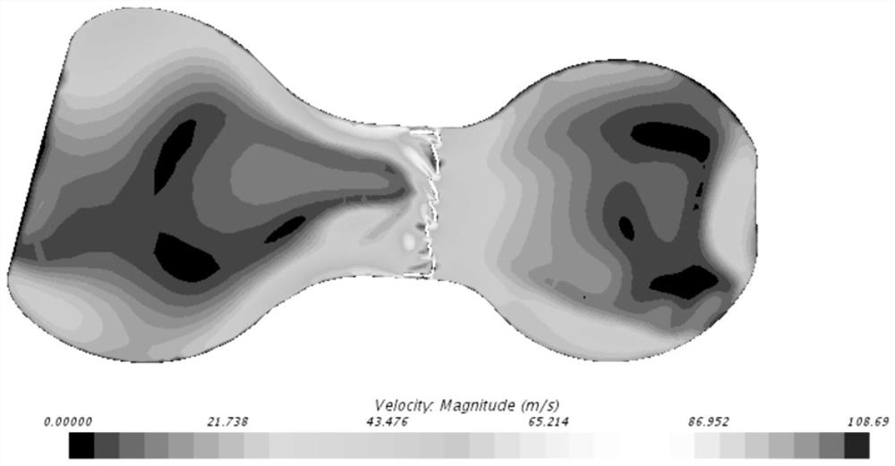
[0034] Such as Figure 4 to Figure 8 As shown, this embodiment is an improvement of Embodiment 1. On the basis of Embodiment 1, this embodiment adds a flow guide assembly, an equal distribution assembly, and a preliminary purification assembly in the housing 1, so that the incoming air flow first passes through the guide flow assembly, and then pass through the equal distribution assembly, so that the gas flowing to the fan mixer body 4 passes through each fan blade on the fan mixer body 4 evenly, and the existence of the fan blade makes the gas flow through the fan mixer body 4 , the gas flows out at an oblique angle, so that there is a dislocation impact with the airflow at the other end of the fan-shaped mixer body 4, avoiding a direct impact that causes a greatly reduced flow rate, thereby increasing the gas flow rate and improving the use value of the fan-shaped mixer body 4

[0035] refer to Figure 4 and Figure 5 , the guide assembly includes a tapered guide rod 11, ...


PUM


Abstract

The invention discloses an exhaust system mixer which comprises a shell. The inner walls of the two sides, located in the middle, of the shell are fixedly connected with the same mounting frame, the inner wall of the mounting frame is fixedly connected with a fan-shaped mixer body, and the outer wall, close to the fan-shaped mixer body, of the mounting frame is fixedly connected with a flow limiting frame. A square mixer is replaced by the fan-shaped mixer body, and gas entering the shell through a gas inlet pipe firstly passes through a flow guide assembly and then passes through a uniform distribution assembly, so that the gas flowing to the fan-shaped mixer body uniformly passes through each fan-shaped blade on the fan-shaped mixer body; and due to the existence of the fan-shaped blades, after the gas flows through the fan-shaped mixer body, the gas flows out at an inclined angle, so that staggered impact is generated between the gas and gas flow at the other end of the fan-shaped mixer body, the situation that the circulation speed is greatly reduced due to straight-face impact is avoided, the gas circulation speed is increased, and the use value of the fan-shaped mixer body is improved.

Description

technical field [0001] The invention relates to the technical field of mixers, in particular to an exhaust system mixer. Background technique [0002] The exhaust system of the vehicle processes the exhaust gas produced by the engine through a variety of exhaust components to reduce emissions and control noise. Usually, the mixer is set upstream of the SCR catalyst and mixes the engine exhaust gas and urea conversion products. To generate non-polluting nitrogen and water vapor to be discharged, thereby reducing the nitrogen oxide content in automobile exhaust. [0003] During the use of the existing exhaust system mixer, the internal structure of the mixer is square. When the gas passes through the square mixer, the pressure on each space point is different because the gas has not been evenly divided, and the pressure between the gases The resistance is large, so that the gas at both ends of the mixer will have an impact in the horizontal direction during the circulation pr...

Claims


Application Information

Patent Timeline
Patent Type & Authority Applications(China)
IPC IPC(8): F01N3/28
CPCF01N3/2892Y02A50/20
Inventor 张志练
Owner 东风佛吉亚排气控制技术有限公司
Why Eureka
Try Eureka