Fuel system of automobile and leakage detection method of fuel system
A technology for fuel systems and automobiles, which is applied in the direction of charging systems, adding non-fuel substances to fuel, and combustion engines, and can solve problems such as false alarms and detection errors
- Summary
- Abstract
- Description
- Claims
- Application Information
AI Technical Summary
Problems solved by technology
Method used
Image
Examples
Embodiment 1
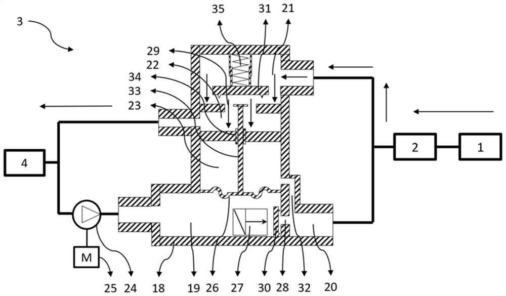
[0057] Figure 3-8 It is a structural diagram of a detector of an embodiment provided in this application. like image 3 As shown, the detector includes a housing 18, and an exhaust passage is provided in the housing 18. A first cavity 21 is arranged on the exhaust passage, and the air inlet of the first cavity 21 is connected with the gas outlet of the fuel vapor recovery tank 2. The air outlet of the first cavity 21 communicates with the air filter 4 through the second cavity 22 , and further communicates with the atmosphere. The air outlet of the first cavity 21 is provided with a first communication port 29, and the first communication port 29 is provided with a first valve core 31, the first valve core 31 is opened and closed by a locking mechanism 35, and the fuel system is realized when opened. Leakage after normal exhaust and leak detection, used for pumping up and maintaining pressure in the fuel system when shutting down.
[0058] Specifically, in the pumping stag...
Embodiment 2
[0074] Considering that the micro solenoid valve will increase the cost of the entire fuel system and the complexity of the control program, the present application provides a detector of another embodiment based on the above embodiments. Figure 9-13 It is a structural diagram of a detector of another embodiment provided in this application. The difference between this embodiment and the above-mentioned embodiment is: first, the drive mechanism of the second valve core 30 is different. In this embodiment, a rebound mechanism 37 is provided on the side of the second valve core 30 facing the second sub-cavity. , the second valve core 30 is opened by the pressure difference between the first sub-cavity 19 and the second sub-cavity 20 , and the second valve core 30 is closed by the rebound mechanism 37 . The cost is reduced by replacing the micro solenoid valve 27 with the rebound mechanism 37 . Second, the vent hole 32 in the above embodiment is eliminated, and a damping hole 3...
Embodiment 3
[0082] The present application also provides a leakage detection method matched with the above-mentioned fuel system. like Figure 14 As shown, the leakage detection method includes the following steps:
[0083] S1410: In response to receiving the leakage detection signal, control the locking mechanism to switch from the second state to the first state, so that the first valve core is closed.
[0084] S1420: Control the pressure regulator to pump air into the fuel system.
[0085] S1430: In response to the pressure of the fuel system reaching a predetermined pressure, the actuator controlling the pressure regulator stops running, and the fuel system enters a pressure maintaining state.
[0086] S1440: Collect the pressure signal of the fuel system within a preset time.
[0087] S1450: Calculate the difference between the earliest pressure value and the latest pressure value within a preset time as a pressure change detection value.
[0088] Subsequently, it is judged wheth...
PUM
 Abstract
Description
Claims
Application Information
 - R&D
- Intellectual Property
- Life Sciences
- Materials
- Tech Scout
- Unparalleled Data Quality
- Higher Quality Content
- 60% Fewer Hallucinations
Browse by: Latest US Patents, China's latest patents, Technical Efficacy Thesaurus, Application Domain, Technology Topic, Popular Technical Reports.
© 2025 PatSnap. All rights reserved.Legal|Privacy policy|Modern Slavery Act Transparency Statement|Sitemap|About US| Contact US: help@patsnap.com


