Tandem blade type centrifugal impeller coupled with full-three-dimensional inducer blade shape

A technology of centrifugal impeller and inducer, which is applied in the direction of non-variable pumps, components of pumping devices for elastic fluids, machines/engines, etc., and can solve the problem of height of spanner small flow channel, aerodynamic performance benefit blade processing cost Conflict with processing technology, limited effect and other issues

Pending Publication Date: 2021-10-22
NORTHWESTERN POLYTECHNICAL UNIV
View PDF10 Cites 0 Cited by
  • Summary
  • Abstract
  • Description
  • Claims
  • Application Information

AI Technical Summary

Problems solved by technology

[0003] Aiming at the problem of uneven flow field caused by the secondary flow inside the centrifugal impeller, people have adopted various measures, such as: blade backward bending, forward tilting, suction air control, casing treatment, etc., these measures have realized on the one hand The improvement of the efficiency and stable working margin of the centrifugal compressor, on the other hand, weakens the working ability of the centrifugal impeller, and its effect is relatively limited or facing a bottleneck in the transonic centrifugal compressor with higher speed and pressure ratio
Aiming at the shock wave control problem of transonic centrifugal compressor, people have developed a full three-dimensional arbitrary space curved surface centrifugal impeller to better adapt to the transonic incoming flow at the impeller inlet. However, due to the small aspect ratio of the traditional centrifugal blade and the highly twisted flow path There is still a large conflict between the aerodynamic performance benefits brought by the full three-dimensional arbitrary space curved surface impeller and the blade processing cost and processing technology. So far, there is no precedent for the practical application of the full three-dimensional arbitrary space curved surface impeller

Method used


Image

  • Tandem blade type centrifugal impeller coupled with full-three-dimensional inducer blade shape
  • Tandem blade type centrifugal impeller coupled with full-three-dimensional inducer blade shape
  • Tandem blade type centrifugal impeller coupled with full-three-dimensional inducer blade shape

Examples


Embodiment Construction

[0020] In describing the present invention, it should be understood that the terms "center", "longitudinal", "transverse", "length", "width", "thickness", "upper", "lower", "front", " Orientation indicated by rear, left, right, vertical, horizontal, top, bottom, inside, outside, clockwise, counterclockwise, etc. The positional relationship is based on the orientation or positional relationship shown in the drawings, which is only for the convenience of describing the present invention and simplifying the description, rather than indicating or implying that the referred device or element must have a specific orientation, be constructed and operated in a specific orientation, Therefore, it should not be construed as limiting the invention.

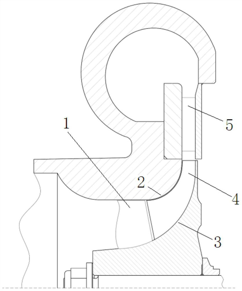
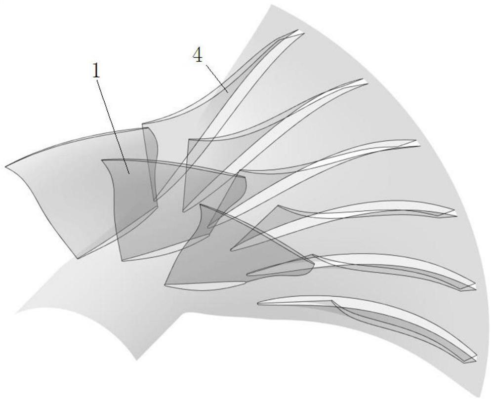
[0021] see Figure 1-Figure 6 , the technical scheme adopted in the present invention is: a tandem-blade centrifugal impeller configuration coupled with a full three-dimensional inducer blade shape, the blades in the initial centrifugal imp...


PUM


Abstract

The invention relates to a tandem blade type centrifugal impeller coupled with a full-three-dimensional inducer blade model, and aims to consider the full-three-dimensional design requirement of a transonic speed centrifugal impeller and the machining and manufacturing cost of the impeller by means of the unique structural advantages of the tandem blade type centrifugal impeller on the basis of the existing machining level. The design advantages of a full-three-dimensional arbitrary space curved surface impeller are reserved, meanwhile, the performance benefits of a tandem blade type centrifugal impeller structure are overlaid, and the effect that 1 + 1 is larger than 2 is achieved.

Description

technical field [0001] The invention belongs to the technical field of small and medium aeroengine / gas turbine compressors, and in particular relates to a tandem blade centrifugal impeller coupled with a full three-dimensional inducer blade shape. Background technique [0002] Compressor technology is one of the most critical and difficult technologies in aero-engines, and its technical level is directly related to the overall development of the engine. Centrifugal compressors are the core components of small and medium-sized aeroengines. Driven by the demand for higher thrust (power) to weight ratios of engines, transonic centrifugal compressors with high load, high pressure ratio and high speed characteristics have gradually become the mainstream of design. However, transonic centrifugal compressors have always faced the design problems of low efficiency and margin level: limited by the objectively existing violent turning of the flow channel and the effects of centrifugal...

Claims


Application Information

Patent Timeline
IPC IPC(8): F04D29/30
CPCF04D29/30
Inventor 李紫良冯鲁文吴艳辉卢新根
Owner NORTHWESTERN POLYTECHNICAL UNIV
Why Eureka
Try Eureka