Bolt propeller

A technology of thrusters and pins, applied in the direction of controlling mechanical energy, electrical components, electromechanical devices, etc., can solve the problems of large structure, waste of ball screw space, complexity, etc., and achieve the effect of reducing volume and realizing telescopic distance.

Inactive Publication Date: 2021-10-22
苏州卓誉电气技术有限公司
View PDF1 Cites 0 Cited by
  • Summary
  • Abstract
  • Description
  • Claims
  • Application Information

AI Technical Summary

Problems solved by technology

[0002] The pin thruster is a driving part that can adjust the telescopic state at any time, and can be used in operating environments such as vehicle transportation, pushing goods, and fixed support; however, the drive motors used in the current pin thrusters all have the disadvantages of large and complex structures;
[0003] For example, the Chinese patent CN201621093672.2 discloses the commonly used motor structure on the market. The structure includes a fixed connection of the front end cover and the rear end cover. The magnetic steel group bonded by the iron core and the magnetic steel and the hollow shaft in the magnetic steel group, the bearings sleeved at both ends of the hollow shaft are erected on the front end cover and the rear end cover respectively; the screw rod of the ball screw pair passes through the front end The cover extends into the hollow shaft of the hollow rotor assembly, and the screw is fixedly connected to the hollow shaft. When the drive rotates, the ball screw only rotates to drive the nut on it to move back and forth, so the ball screw is located in the space inside the motor. Cause waste, so that miniaturization requirements cannot be achieved

Method used


Image

  • Bolt propeller
  • Bolt propeller
  • Bolt propeller

Examples


Embodiment Construction

[0026] In order to make the above objects, features and advantages of the present invention more comprehensible, specific implementations of the present invention will be described in detail below in conjunction with the accompanying drawings. In the following description, numerous specific details are set forth in order to provide a thorough understanding of the present invention. However, the present invention can be implemented in many other ways different from those described here, and those skilled in the art can make similar improvements without departing from the connotation of the present invention, so the present invention is not limited by the specific embodiments disclosed below.

[0027] It should be noted that when an element is referred to as being “fixed” to another element, it can be directly on the other element or there can also be an intervening element. When an element is referred to as being "connected to" another element, it can be directly connected to t...


PUM


Abstract

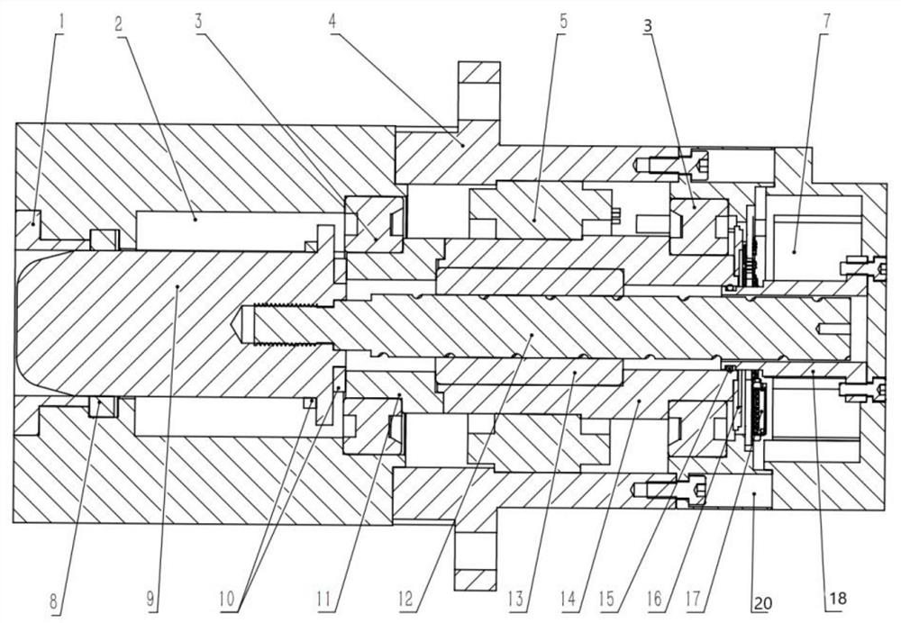
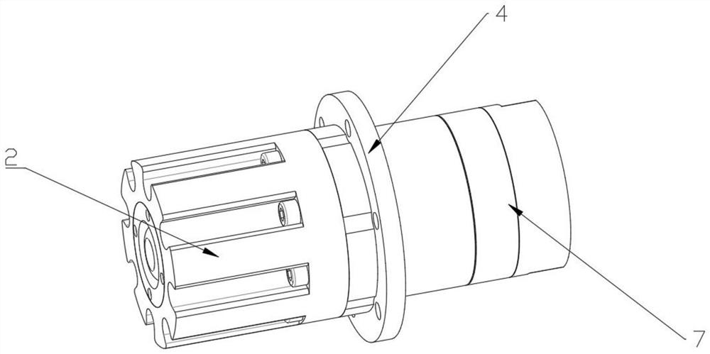
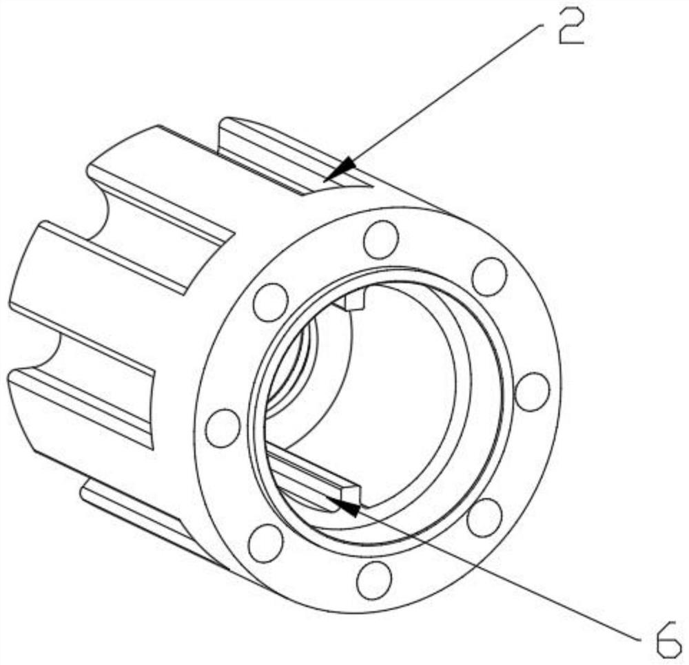
The invention discloses a bolt propeller which comprises a motor shell. A frameless torque motor is arranged in the motor shell, a nut and a nut adapter are arranged in the frameless torque motor, the nut is in transmission connection with the frameless torque motor through the nut adapter, and a lead screw matched with the nut is arranged in the nut. The bolt propeller further comprises a guide pushing column arranged a the extending end of the lead screw. According to the structural design, a driving rod in a traditional motor is omitted, the lead screw is directly installed in the motor, utilization of the length space in the motor is achieved, and therefore the size of the device is greatly reduced.

Description

technical field [0001] The invention relates to the field of thrusters, in particular to a bolt thruster. Background technique [0002] The pin thruster is a driving part that can adjust the telescopic state at any time, and can be used in vehicle transportation, pushing goods, fixed support and other operating environments; however, the drive motors used in the current pin thrusters all have the disadvantages of large and complex structures; [0003] For example, Chinese patent CN201621093672.2 discloses the motor structure commonly used in the market. The structure includes a fixed connection of the front end cover and the rear end cover. The stator is fixed inside the motor. The hollow rotor assembly is installed in the stator. The magnetic steel group bonded by the iron core and the magnetic steel and the hollow shaft in the magnetic steel group, the bearings sleeved at both ends of the hollow shaft are erected on the front end cover and the rear end cover respectively; ...

Claims


Application Information

Patent Timeline
Patent Type & Authority Applications(China)
IPC IPC(8): F16H25/24H02K7/06H02K11/21
CPCF16H25/24H02K7/06H02K11/21F16H2025/2075
Inventor 苏瑞汤鑫
Owner 苏州卓誉电气技术有限公司
Why Eureka
Try Eureka