Magnetic gate valve

A gate valve and magnetic technology, applied in the field of magnetic gate valves, can solve the problems of long time, troublesome gate valve assembly and maintenance, etc., and achieve the effect of easy automatic reset, easy assembly and maintenance, and shortening the time of disassembly and assembly.

Active Publication Date: 2021-10-22
TAIZHOU JINGAN PIPE IND CO LTD
View PDF13 Cites 4 Cited by
  • Summary
  • Abstract
  • Description
  • Claims
  • Application Information

AI Technical Summary

Problems solved by technology

[0004] The inventor believes that when disassembling and maintaining the gate valve, it takes a long time to twist the bolts or nuts, which makes the assembly and maintenance of the gate valve more troublesome

Method used


Image

  • Magnetic gate valve
  • Magnetic gate valve
  • Magnetic gate valve

Examples


Embodiment Construction

[0037] The following is attached Figure 1-3 The application is described in further detail.

[0038] The embodiment of the present application discloses a magnetic gate valve.

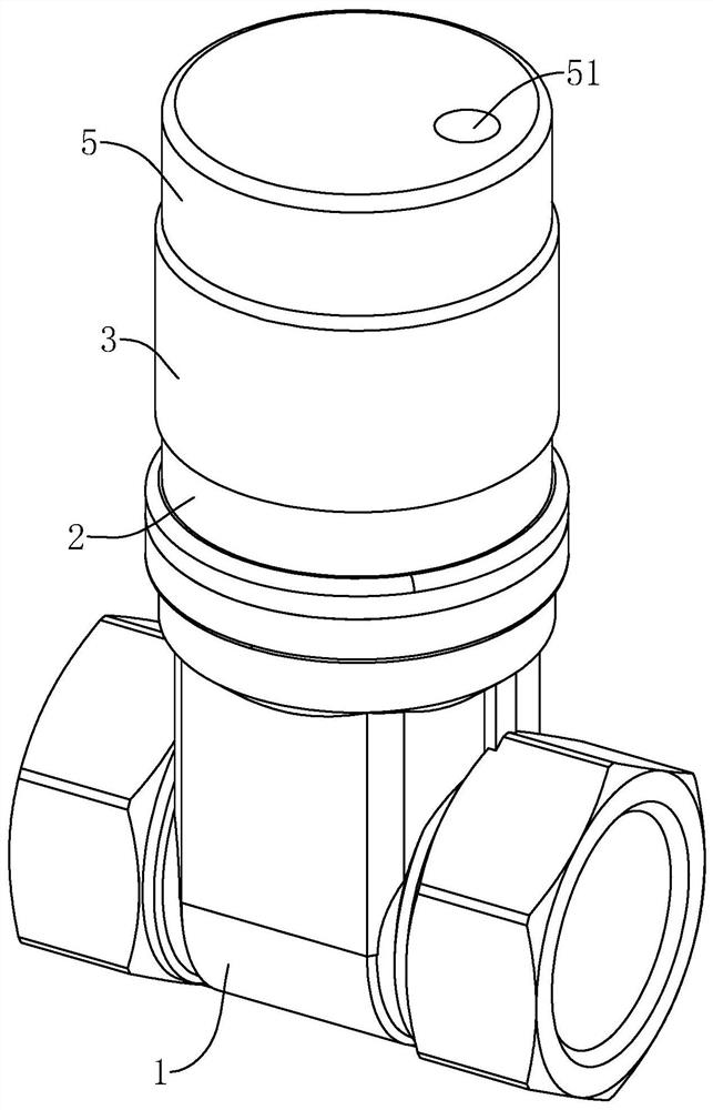
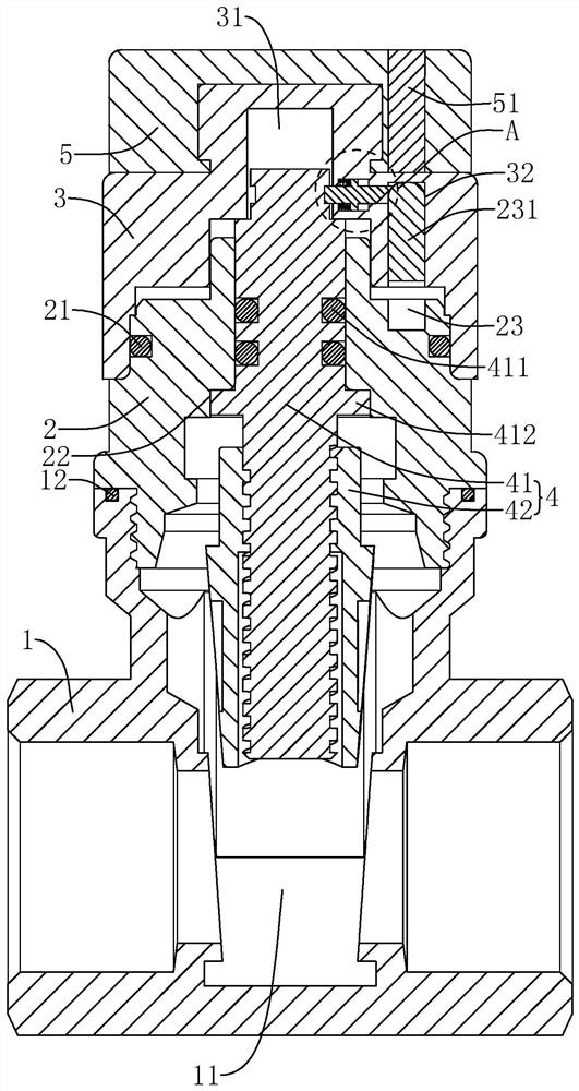
[0039] refer to figure 1 with figure 2 The magnetic gate valve includes a valve body 1, a valve sleeve 2, a valve cap 3, and a valve core 4. The valve body 1 is in the shape of a three-way valve, and the valve sleeve 2 is threadedly connected to the valve port in the middle part of the valve body 1. And rotatably connected to the end of the valve sleeve 2 away from the valve body 1, the valve core 4 slides in the valve body 1 and the valve sleeve 2 along the direction perpendicular to the fluid flow in the valve body 1, and the valve body 1 is provided with a valve core 4 sliding The valve chamber 11 slides in and out, and the rotation of the bonnet 3 can drive the valve core 4 to slide to close or open the valve chamber 11.

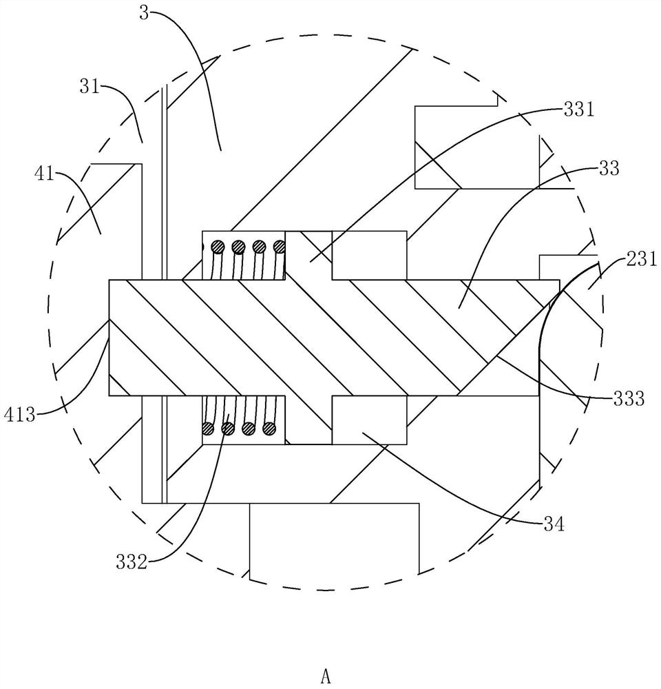
[0040] refer to figure 2 A seal ring 3 12 is embedded on the end surfa...


PUM


Abstract

The invention relates to a magnetic gate valve, and relates to the technical field of valves. The magnetic gate valve comprises a valve body, a valve sleeve in threaded connection with the valve body, and a bonnet which is arranged on the valve sleeve in a sleeving mode and rotates on the valve sleeve, a valve element which slides in the valve sleeve is glidingly arranged in the valve body, a valve cavity allowing the valve element to slide is formed in the valve body, the bonnet is used for driving the valve element to slide to close and open the valve cavity, the bonnet and the valve element are detachably connected, the circumferential side wall of the valve sleeve is sleeved with a first sealing ring, and the first sealing ring glidingly abuts against the inner side wall of the bonnet. Through arrangement of the valve sleeve, through threaded connection of the valve sleeve and the valve body and mutual sleeving of the valve sleeve and the bonnet, the bonnet, the valve sleeve and the valve body are detachably connected, so that the valve element is conveniently taken out of the valve cavity, the disassembling and assembling time of the gate valve is shortened, and the gate valve has the advantage that the gate valve is convenient to assemble and maintain.

Description

technical field [0001] The present application relates to the technical field of valves, in particular to a magnetic gate valve. Background technique [0002] At present, the gate valve is a gate of the opening and closing part, and the movement direction of the gate is perpendicular to the direction of the fluid. The gate valve can only be fully opened and fully closed, and cannot be adjusted and throttled like a control valve. In order to ensure the stability of the gate valve after operation, a magnetic gate valve is used to unlock the rotation of the gate valve through the attraction of the magnetic parts. [0003] Usually, the gate valve is equipped with some equipment that needs to control on-off, while the traditional gate valve is connected by bolts and nuts during the assembly process, and the bolts or nuts need to be loosened in the process of disassembly and maintenance to connect the various parts of the gate valve to split. [0004] The inventor believes that ...

Claims


Application Information

Patent Timeline
Patent Type & Authority Applications(China)
IPC IPC(8): F16K3/12F16K3/314F16K35/16F16K41/04
CPCF16K3/12F16K3/314F16K41/04F16K35/16Y02E10/20
Inventor 毛礼国
Owner TAIZHOU JINGAN PIPE IND CO LTD
Why Eureka
Try Eureka