Automatic track spacing detection device and detection method

An automatic detection device and track spacing technology, which is applied in the direction of measuring devices, electromagnetic measuring devices, and electrical devices, can solve the problems of inability to provide accurate alarm prompts, fail to meet the use requirements, and low degree of automation, and achieve convenient track maintenance. , high degree of automation, and the effect of reducing labor intensity

Active Publication Date: 2021-10-22
CRRC QINGDAO SIFANG CO LTD
View PDF7 Cites 0 Cited by
  • Summary
  • Abstract
  • Description
  • Claims
  • Application Information

AI Technical Summary

Problems solved by technology

[0004] The detection equipment in the prior art has a simple structure and a low degree of automation. Manual hand-held detection equipment is often required for mobile detection, which is labor-intensive, and when abnormalities are detected, accurate alarm prompts cannot be performed, and missed or wrong detections are prone to occur. situation, unable to meet the requirements for use

Method used


Image

  • Automatic track spacing detection device and detection method
  • Automatic track spacing detection device and detection method
  • Automatic track spacing detection device and detection method

Examples


Embodiment 1

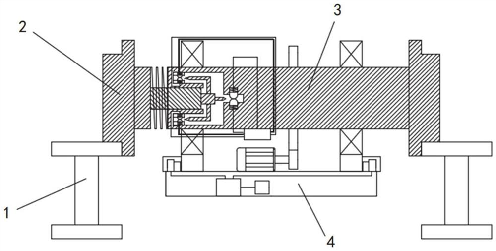
[0030] According to an embodiment of the present invention, an embodiment of an automatic track spacing monitoring device is provided, refer to Figure 1-Figure 5 , including: a driving shaft 3 and rollers 2 arranged at both ends of the driving shaft 3; the rollers 2 at both ends are respectively arranged on two I-shaped rails 1, and can move along the rails.

[0031] The lower side of drive shaft 3 is equipped with console 4, and console 4 is respectively provided with control unit 48, driving mechanism, positioning unit and image acquisition unit; Control unit 48 is connected with driving mechanism, positioning unit and image acquisition unit respectively; Positioning The unit and the image acquisition unit are used to realize the position positioning and image acquisition of the detected track, and upload the collected data to the control unit 48, record the data, and facilitate maintenance; the entire track spacing automatic monitoring device is compact in structure, high i...

Embodiment 2

[0051] According to an embodiment of the present invention, an embodiment of an automatic track spacing detection method is disclosed. The method is implemented based on the track spacing automatic monitoring device in Embodiment 1, and specifically includes the following process:

[0052] When the track spacing automatic monitoring device works normally, the driving shaft 3 drives the roller 2 to roll along the two track bodies;

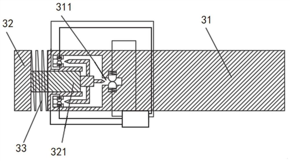
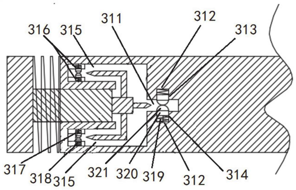
[0053] When the distance between the two tracks is reduced, the roller 2 is squeezed, the first spring 33 is compressed, and the distance between the first shaft body and the second shaft body is reduced;

[0054] The first insulating insertion rod 323 is inserted between the first conductive member 313 and the second conductive member 314, so that the first conductive member 313 and the second conductive member 314 are disconnected, an alarm is triggered, and an alarm position is located and an image is collected at the same time.

[0055] When the...


PUM


Abstract

The invention discloses an automatic track spacing detection device and method. The automatic track spacing detection device comprises a driving shaft and rolling wheels arranged at the two ends of the driving shaft. The driving shaft comprises a first shaft body and a second shaft body, and a first spring is arranged between the first shaft body and the second shaft body. An opening is formed in the end, opposite to the second shaft body, of the first shaft body, and a first conductive part and a second conductive part which are in contact with each other are arranged in the opening. A detection sliding rod extending into the opening is connected to the second shaft body, and a first insulating insertion rod is connected to the front end of the detection sliding rod. The first insulating insertion rod can be inserted between the first conductive part and the second conductive part when the distance between the first shaft body and the second shaft body is reduced so as to block the electrical connection between the first conductive part and the second conductive part. According to the invention, efficient detection of too large and too small track spacing can be realized, the automation degree is high, the contact is accurate, and the phenomena of wrong detection and missing detection are avoided.

Description

technical field [0001] The invention relates to the technical field of automatic track detection, in particular to an automatic track distance detection device and detection method. Background technique [0002] The statements in this section merely provide background information related to the present invention and do not necessarily constitute prior art. [0003] Rail transit is a vehicle transportation system that uses rail structures for load-bearing and guidance. According to the requirements of the overall planning of urban transportation, a fully enclosed or partially enclosed dedicated track line is set up to transport a considerable amount of passenger traffic in the form of trains or bicycles. At present, most rail transits use two I-shaped tracks arranged side by side. For the two I-shaped tracks, special equipment will be used to detect the distance between them before delivery. [0004] The detection equipment in the prior art has a simple structure and a low d...

Claims


Application Information

Patent Timeline
Patent Type & Authority Applications(China)
IPC IPC(8): G01B7/14G01B7/34
CPCG01B7/14G01B7/34Y02E10/50
Inventor 李智国宋龙龙周平宇弓海斌史小利
Owner CRRC QINGDAO SIFANG CO LTD
Why Eureka
Try Eureka