Device and method for testing strain position of object by using external strain

A testing device and testing method technology, applied in the direction of measuring devices, optical devices, instruments, etc., can solve the problem of no real-time monitoring and calculation methods, and achieve the effect of real-time monitoring and calculation and solving cumulative errors.

Active Publication Date: 2021-10-22
ZHEJIANG UNIV
View PDF16 Cites 0 Cited by
  • Summary
  • Abstract
  • Description
  • Claims
  • Application Information

AI Technical Summary

Problems solved by technology

[0008] 2) There is no real-time monitoring and calculation method for the position corresponding to the calibration of the stress position on the surface

Method used


Image

  • Device and method for testing strain position of object by using external strain
  • Device and method for testing strain position of object by using external strain
  • Device and method for testing strain position of object by using external strain

Examples


Embodiment Construction

[0063] The present invention will be further described below in conjunction with drawings and embodiments.

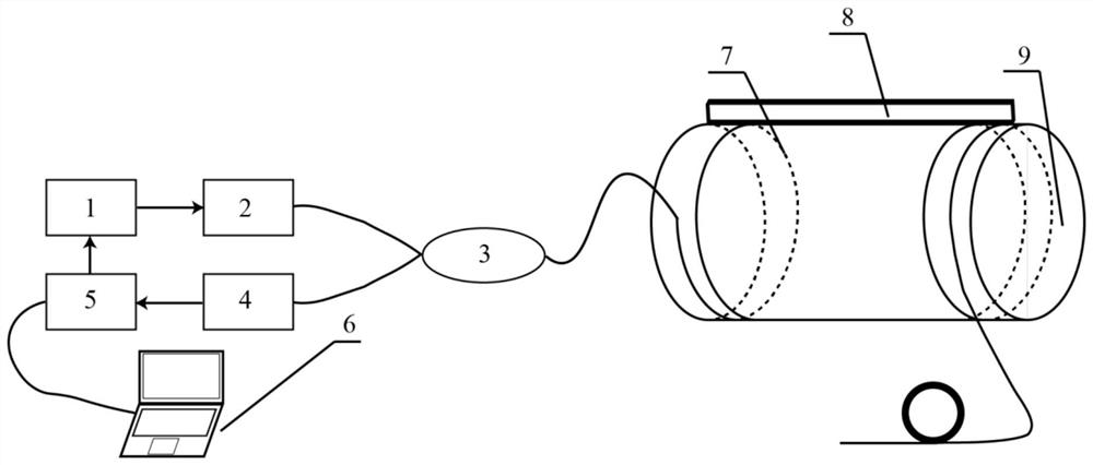
[0064] Such as figure 1 As shown, the device includes a light source driving circuit 1, a light source 2, a 2×2 optical coupler 3, a photodetector 4, a sensing fiber 7 and a strain applying device 8; the light source driving circuit 1 is connected to the light source 2, and the light output of the light source 2 The end is connected to one end on one side of the 2×2 optical coupler 3, the other end on one side of the 2×2 optical coupler 3 is connected to the photodetector 4, and the other end on the other side of the 2×2 optical coupler 3 is connected to the sensing fiber 7, the other end of the other side of the 2×2 optical coupler 3 and the other end of the sensing fiber 7 are used as empty ports to connect to the pigtail. The strain applying device 8 is a strip-shaped object that can be made of any material and is attached to a certain circumferential position in th...


PUM


Abstract

The invention discloses a device and a method for testing a strain position of an object by using external strain. A light source driving circuit is connected with a light source, the light source, the photoelectric detector and the sensing optical fiber are all connected to the 2 * 2 optical coupler, and the sensing optical fiber is tightly wound on the surface of a measured object; calibration between the position of the wound sensing optical fiber and the detection time is achieved through an external stress applying device, and the conversion error caused by purely depending on the measurement time, the optical fiber stress position and the object stress position is eliminated; and the relationship between the one-dimensional coordinate of the optical fiber and the two-dimensional coordinate of the surface of the measured object is established, and the measurement of the strain position of the object is realized more accurately. The device and the method are used for any complex surface including a variable-diameter object, and solve the problem of accumulated errors caused by directly utilizing a curved surface shape to correspond to the one-dimensional length of the optical fiber traditionally.

Description

technical field [0001] The invention relates to a device and a method how to test the strain position of an object, in particular to a device and a method for testing the strain position of an object by using an external strain. Background technique [0002] Optical time domain reflectometry has the advantages of wide monitoring range, continuous distribution, large response bandwidth, and adaptability to harsh environments. It uses backscattered signals in optical fibers to perform long-distance distributed measurement. It is used in ultra-long-distance environmental monitoring to monitor changes in the external environment. [0003] In the prior art, the actual position of the strain of the object is usually judged by the time difference of backscattering. The distance L in the optical fiber and the detection time t of the backscattered light intensity signal at this point after the self-pulse light is emitted have the following relationship: [0004] L=t·c / n [0005] Am...

Claims


Application Information

Patent Timeline
Patent Type & Authority Applications(China)
IPC IPC(8): G01B11/16
CPCG01B11/16
Inventor 陈杏藩刘一石
Owner ZHEJIANG UNIV
Why Eureka
Try Eureka