Method for accurately positioning the position of a workpiece on a machine tool and visual system

A technology of precise positioning and machine tool coordinate system, which is applied to computer components, image data processing, instruments, etc., can solve the problems of low positioning efficiency, time required, and large uncertainty in workpiece positioning operations, and achieve fast and accurate positioning, save The effect of positioning time

Pending Publication Date: 2021-10-22
柔胜刚智能科技苏州有限公司
View PDF0 Cites 5 Cited by
  • Summary
  • Abstract
  • Description
  • Claims
  • Application Information

AI Technical Summary

Problems solved by technology

[0005] (1) The direct alignment method depends on the level of the alignment workers, and there is great uncertainty in the actual workpiece positioning operation;
[0006] (2) The positioning of the marking and alignment method is limited by the marking accuracy and alignment accuracy, so that the positioning accuracy of the workpiece is not high;
[0007] (3) The use of fixture positioning requires placing the workpiece at a specific position for positioning, which takes time and the positioning efficiency is low

Method used


Image

  • Method for accurately positioning the position of a workpiece on a machine tool and visual system
  • Method for accurately positioning the position of a workpiece on a machine tool and visual system
  • Method for accurately positioning the position of a workpiece on a machine tool and visual system

Examples


Embodiment 1

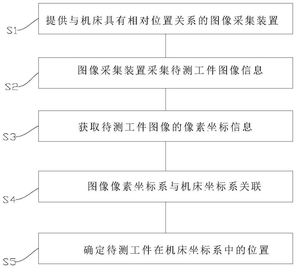
[0088] A precise positioning method for the position of a workpiece on a machine tool, which is used for associating the workpiece to be measured with the coordinate system of the machine tool, comprising the following steps:

[0089] S1: Provide an image acquisition device that has a relative positional relationship with the machine tool; the image acquisition device in this embodiment is an industrial camera. Set at least the first positioning point and the second positioning point, and use the first positioning point as the origin of the machine tool coordinates; then adjust the industrial camera to a height where the field of view of the photo is at least enough to include the first positioning point and the second positioning point.

[0090]The specific parameters of the camera in this embodiment are that the field of view of the image is 500mm×500mm, the distance between the camera and the object to be measured is 500mm, and the measurement accuracy of the image should re...

Embodiment 2

[0118] A precise positioning method for the position of a workpiece on a machine tool, which is used for associating the workpiece to be measured with the coordinate system of the machine tool, comprising the following steps:

[0119]S1: Provide an image acquisition device that has a relative positional relationship with the machine tool; the image acquisition device in this embodiment is an industrial camera. Set at least the first positioning point and the second positioning point, and use the first positioning point as the origin of the machine tool coordinates; then adjust the industrial camera to a height where the field of view of the photo is at least enough to include the first positioning point and the second positioning point.

[0120] The specific parameters of the camera in this embodiment are that the field of view of the image is 500mm×500mm, the distance between the camera and the object to be measured is 500mm, and the measurement accuracy of the image should re...

Embodiment 3

[0185] This embodiment proposes a machine tool, including a machine tool body, an image acquisition device and a processor for manipulating the machine tool to drive it to perform vector motion, and the processor executes the precise positioning of the workpiece on the machine tool in the above-mentioned embodiment 1 or embodiment 2 method. The precise positioning method of the position of the workpiece on the machine tool can enable the rapid and accurate positioning of the position of the workpiece on the machine tool. It is worth mentioning that a machine tool also includes a supplementary light device. The supplementary light device includes a mobile bracket and a light source. The light source is installed on the mobile bracket, and the mobile bracket is placed at a suitable position on the machine tool. . A supplementary light device is added outside the machine tool, and the light source is irradiated on the workpiece, highlighting the edge features of the workpiece to...


PUM


Abstract

The invention provides a method for accurately positioning the position of a workpiece on a machine tool. The method comprises the following steps that: S1, an image acquisition device having a relative position relationship with the machine tool is provided; S2, a to-be-detected workpiece in a multi-point manner is collected through an image collection device, and multi-point image information of the to-be-detected workpiece on the machine tool operation table is obtained; S3, image splicing is carried out on the image information in the step S2, then contour information of the workpiece is extracted, and pixel coordinate information of a workpiece image is obtained; S4, the correlation between the pixel coordinate system of the workpiece image and the machine tool coordinate system is obtained by determining the correlation information of the camera coordinate system and the machine tool coordinate system and the correlation information of the pixel coordinate system of the workpiece image and the camera coordinate system where the image acquisition device is located; and S5, accurate positioning information of the workpiece at the position of the machine tool coordinate system is determined. Workpieces do not need to be moved, the time for manually moving large workpieces for positioning is saved, and positioning can be rapidly and accurately achieved.

Description

technical field [0001] The invention relates to the technical field of workpiece processing equipment, in particular to a precise positioning method and a vision system for a workpiece on a machine tool. Background technique [0002] Nowadays, mechanized processing is applied in more and more fields. With the development of society, various industries have higher and higher requirements for the precision of machine tool products. In order to improve the machining accuracy of workpieces, the first thing is to obtain the precise positioning of the workpiece on the machine tool , in the follow-up operation. [0003] In the existing technology, the positioning of the workpiece on the machine tool includes the following three methods: 1. Direct alignment method positioning: directly align the workpiece processing surface on the machine tool by using methods such as dial indicators, scratch needles or visual inspection during direct alignment method positioning 2. Scribing alignm...

Claims


Application Information

Patent Timeline
Patent Type & Authority Applications(China)
IPC IPC(8): G06T7/73G06T7/80G06T5/00G06K9/46G06K9/62
CPCG06T7/73G06T7/85G06T2207/10004G06T2207/30164G06T2207/30244G06F18/22G06F18/24147G06T5/90G06T5/70
Inventor 李智曾继跃张仕进
Owner 柔胜刚智能科技苏州有限公司
Why Eureka
Try Eureka