Die bonding mechanical arm and die bonding equipment
A robotic arm and die-bonding technology, applied in conveyor objects, semiconductor/solid-state device manufacturing, semiconductor devices, etc., can solve the problem of lack of high-efficiency die-bonding solutions, and achieve the effect of high die-bonding efficiency
- Summary
- Abstract
- Description
- Claims
- Application Information
AI Technical Summary
Problems solved by technology
Method used
Image
Examples
Embodiment 1
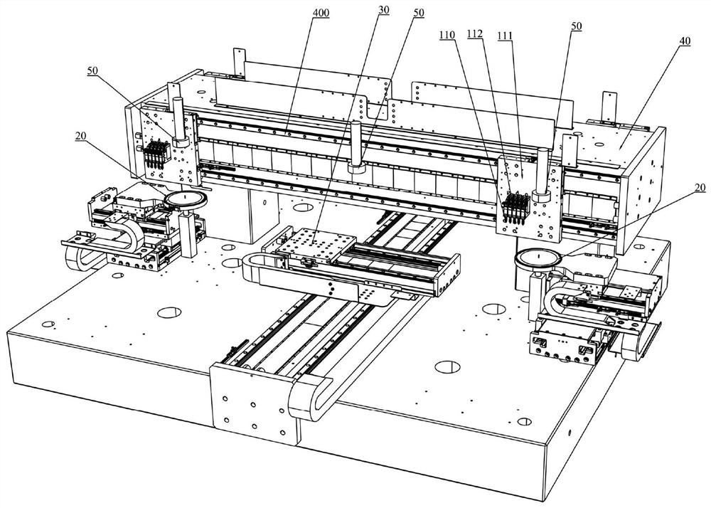
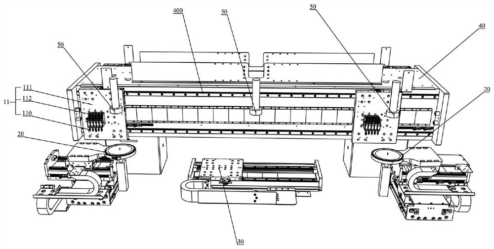
[0035] In this example, if figure 1 and figure 2 As shown, the die bonding robotic arm 10 includes a base 11 and a first driving mechanism. The first driving mechanism is used to drive the substrate 11 to move between the wafer plate 20 for placing the wafer and the stage 30 for placing the target substrate. A plurality of die bonding heads 110 are arranged on the substrate 11 , and the plurality of die bonding heads 110 are arranged in m rows and n columns; wherein, m≧1, n≧2, and m and n are integers. Each die-bonding head 110 includes a lifting mechanism and a suction nozzle. The suction nozzle is arranged on the lifting mechanism. The lifting mechanism is used to drive the suction nozzle to lift up and down. The suction nozzle can suck the wafer.
[0036] The above-mentioned die-bonding robotic arm provided in this embodiment has a plurality of die-bonding heads 110 arranged on the substrate 11, and the plurality of die-bonding heads 110 are arranged in an array form of ...
Embodiment 2
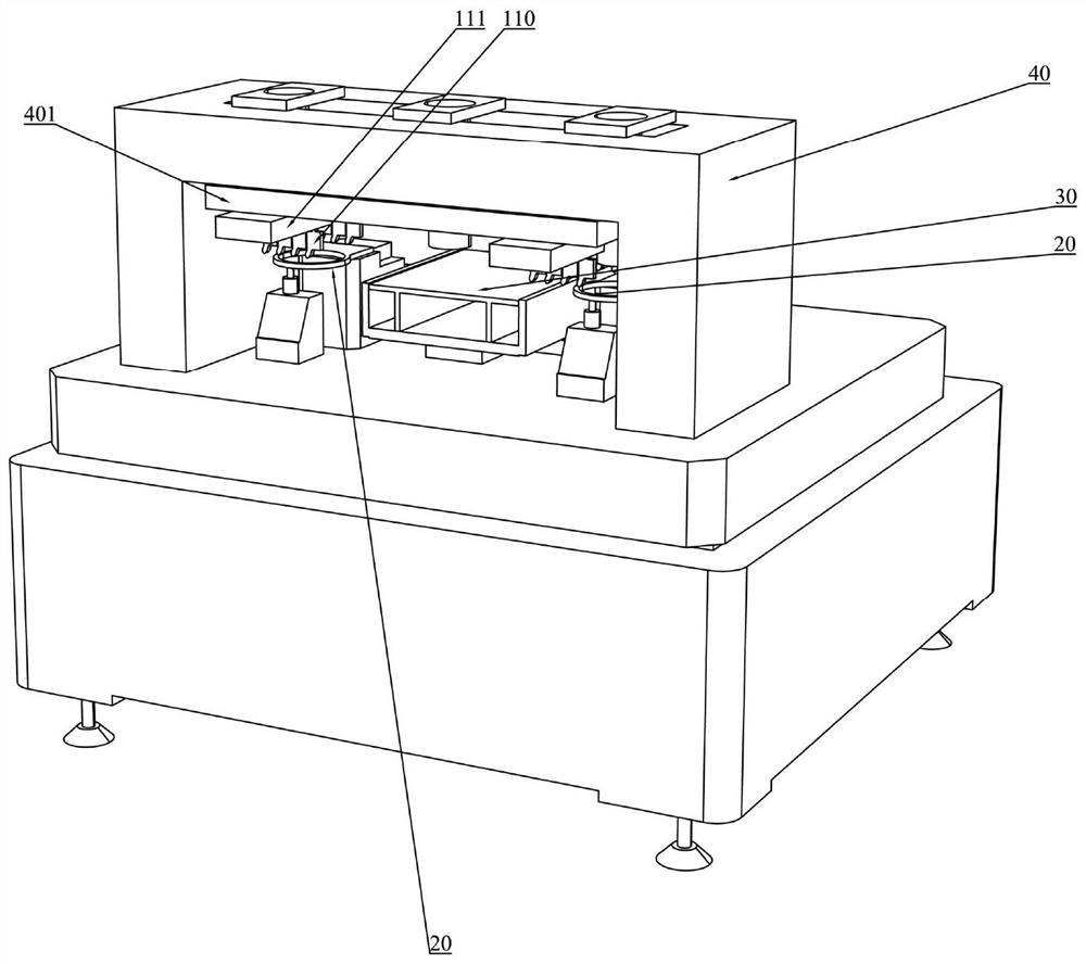
[0043] In this embodiment, the slide rails provided on the mounting frame 40 are different from the above-mentioned Embodiment 1. Specifically, refer to image 3 and Figure 4 , the mounting frame 40 is provided with a first-level slide rail extending along the first direction (not shown in the figure, blocked by the sliding platform 401), the first-level slide rail is provided with a sliding platform 401, and the sliding platform 401 is provided with a sliding platform 401 extending along the first direction. Secondary sliding rails extending in two directions (not shown in the figure, covered by the mounting plate 111 ). The base body 11 includes a mounting plate 111 disposed on the secondary slide rail and capable of sliding along the secondary slide rail. The first driving mechanism is connected with the mounting plate 111 and is used to drive the mounting plate 111 to move along the secondary slide rail, and drive the sliding platform 401 to move along the primary slide ...
Embodiment 3
[0059] In this embodiment, it is different from the above-mentioned embodiment 1 and embodiment 2, such as Figure 5 As shown, the crystal bonding equipment further includes a second image acquisition device 60, and each crystal bonding head 110 of the crystal bonding robotic arm also includes a rotating mechanism.
[0060] The second image acquisition device 60 is used for acquiring images of the sucked wafers after the wafers are picked up by the suction nozzles. Specifically, the image collection mechanism may be a CCD camera, etc., and the images collected by it may be static photos, dynamic video information, or real-time video surveillance images. According to the images collected by the image acquisition mechanism, after the suction nozzle picks up the wafer, the angle presented by the sucked wafer on the suction nozzle can be judged, and the angle can be evaluated to determine whether the angle of the wafer can be accurately aligned and mounted on the suction nozzle. ...
PUM
 Abstract
Description
Claims
Application Information
 - R&D
- Intellectual Property
- Life Sciences
- Materials
- Tech Scout
- Unparalleled Data Quality
- Higher Quality Content
- 60% Fewer Hallucinations
Browse by: Latest US Patents, China's latest patents, Technical Efficacy Thesaurus, Application Domain, Technology Topic, Popular Technical Reports.
© 2025 PatSnap. All rights reserved.Legal|Privacy policy|Modern Slavery Act Transparency Statement|Sitemap|About US| Contact US: help@patsnap.com


