Line loss compensation circuit
A line loss compensation and circuit technology, applied in the direction of electrical components, adjusting electrical variables, instruments, etc., can solve the problems of complex wiring, high cost, narrow application range, etc., to reduce complexity, reduce development costs, and solve output voltage accuracy Larger offset effects
- Summary
- Abstract
- Description
- Claims
- Application Information
AI Technical Summary
Problems solved by technology
Method used
Image

Examples
no. 1 example
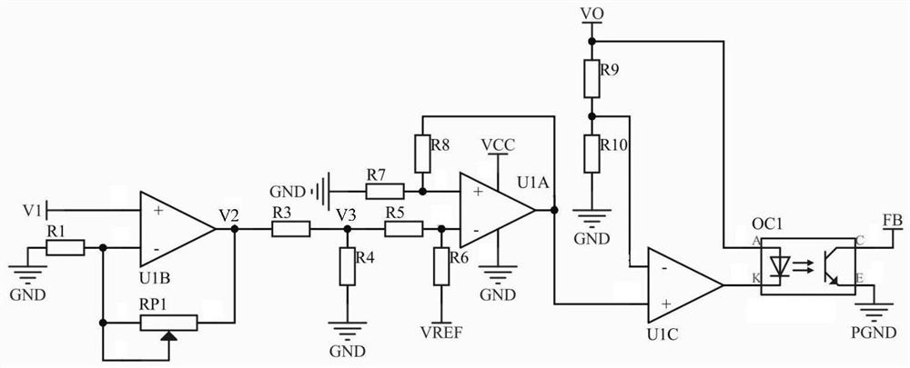
[0030] figure 1 The line loss compensation circuit structure shown in the first embodiment of the present invention includes a line loss compensation circuit of the present embodiment comprises a sample amplifying circuit, a voltage dividing circuit, and an addition circuit.
[0031] The sampling amplifying circuit includes an op amp U1B, the resistor R1, and the adjustable resistor RP1, and the same phase input of the op amp U1B is used to input the sampling voltage V1, one end of the resistor R1, and the other end of the resistor R2 simultaneously connects the inversion of the U1B. One end of the end and resistor RP1, the output of the output terminal of the op amp U1B and the other end of the resistor RP1 are connected together, and the relationship between the voltage V2 and the sampling voltage V1 is as follows:
[0032]
[0033] Where R1 is the resistance value of the resistor R1, RP1 is the resistance of the resistor RP1.
[0034] The voltage dividing circuit includes a ...
no. 2 example
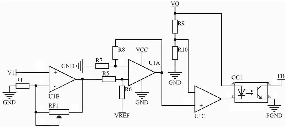
[0059] like figure 2 The application schematic diagram of the line loss compensation circuit of the second embodiment of the present invention is shown in the switching power source, and the present embodiment and the first embodiment differ in that the voltage division circuit is removed, and the compensation range can be further enlarged, for the power source The output end to the device-side impedance, the amount of compensation is required, and the voltage V1 outputted by the sample amplification circuit can be directly used as the compensation voltage.
no. 3 example
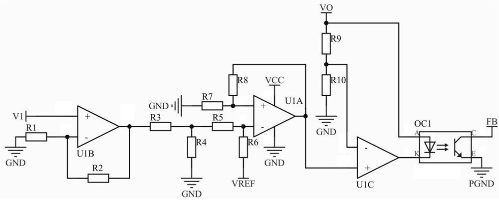
[0061] like image 3 The application schematic diagram of the line loss compensation circuit of the third embodiment of the present invention is shown in the switching power supply, and the present embodiment differs from the first embodiment to replace the adjustable resistor RP1 to a resistor R2 of the fixed resistance. This embodiment is suitable for the case where the line impedance is fixed, and the adjustable resistance is changed to a fixed resistance, and the mechanical external force can be reduced, resulting in a change in adjustable resistance resistance, increase the consistency of the switching power supply, and improve the compensation accuracy and stability of the switching power supply. sex.
PUM
 Abstract
Description
Claims
Application Information