Multi-cavity efficient cooling structure of turbine rotor blade and cooling method of multi-cavity efficient cooling structure

A technology of turbine rotor and cooling structure, which is applied to the supporting elements of blades, engine elements, machines/engines, etc., can solve the problems of poor utilization rate of cold air, prone to backflow stagnation, and high temperature, and achieves a high level of withstand strength, The effect of high strength life level and high air-conditioning utilization rate

Active Publication Date: 2021-10-26
AECC HUNAN AVIATION POWERPLANT RES INST
View PDF6 Cites 0 Cited by
  • Summary
  • Abstract
  • Description
  • Claims
  • Application Information

AI Technical Summary

Problems solved by technology

like figure 1 The radial multi-cavity straight channel shown has the worst cooling air utilization rate, and the higher the RIT is, the more cooling air needs to be used, which is not good for engine performance; figure 2 In order to reduce the temperature of the leading edge of the rotor blade, the structure shown in the figure sets an independent radial single-cavity cooling at the leading edge, which also has the problem of underutilization of the cold air. At the same time, the stagnant backflow zone is prone to appear in the middle and rear three cavities, especially at the bottom of the second partition , so that the temperature of the same part on the outer surface of the blade is higher, which is not good for the life of the engine; Figure 3-4 The three-chamber meandering flow structure shown not only has the problem of backflow stagnation at the bottom of the first chamber or the third chamber, but also has the problem that the leading edge or trailing edge cannot be sufficiently cooled ( image 3 The intermediate cooling gas flows from the bottom of the trailing edge of the blade to the front of the blade so that the cooling of the leading edge is not sufficient, Figure 4 The cooling gas flows from the bottom of the leading edge of the blade to the trailing edge of the blade so that the cooling of the trailing edge is insufficient)
At the same time, the structures shown above all have the problem of large flow loss in the transverse ribs

Method used


Image

  • Multi-cavity efficient cooling structure of turbine rotor blade and cooling method of multi-cavity efficient cooling structure
  • Multi-cavity efficient cooling structure of turbine rotor blade and cooling method of multi-cavity efficient cooling structure
  • Multi-cavity efficient cooling structure of turbine rotor blade and cooling method of multi-cavity efficient cooling structure

Examples


Embodiment Construction

[0036] In order to make the purpose, technical solutions and advantages of the embodiments of the present invention more clear, the technical solutions in the embodiments of the present invention will be clearly and completely described below in conjunction with the accompanying drawings in the embodiments of the present invention. Obviously, the described embodiments It is a part of embodiments of the present invention, but not all embodiments. Based on the embodiments of the present invention, all other embodiments obtained by persons of ordinary skill in the art without making creative efforts belong to the protection scope of the present invention.

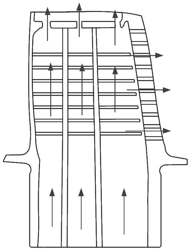
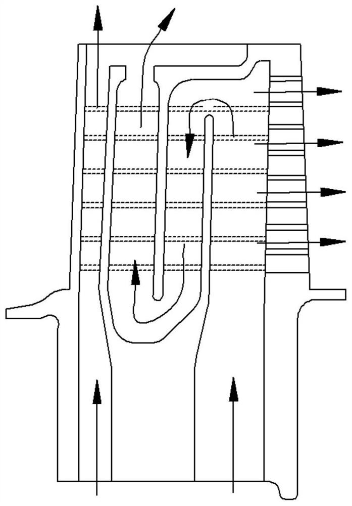
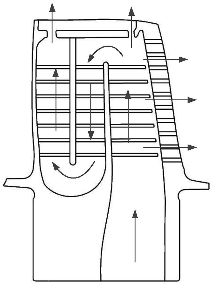
[0037] The multi-cavity efficient cooling structure of the turbine rotor blade of the embodiment of the present invention, such as Figure 5 As shown, the blade 1 includes a tenon and a blade body that penetrates and is fixedly connected with the tenon, and the cooling structure includes a first partition 3, a second partition...


PUM


Abstract

The invention discloses a multi-cavity efficient cooling structure of a turbine rotor blade and a cooling method of the multi-cavity efficient cooling structure. The cooling structure comprises a first partition plate, a second partition plate and a third partition plate which are arranged in an inner cavity of a blade body and are sequentially and fixedly arranged from the front edge of the blade body to the tail edge of the blade body, wherein the side, close to the front edge of the blade body, of the first partition plate longitudinally extends in the direction of a tenon and forms a first cold air channel with the inner wall of the front edge of the tenon; and the side, away from the front edge of the blade body, of the first partition plate transversely extends to the lower part of the second partition plate and the lower part of the third partition plate, longitudinally extends in the direction of the tenon and forms a second cold air channel with the inner wall of the tail edge of the tenon. According to the multi-cavity efficient cooling structure, flow separation can be effectively restrained, the bearable strength level is high, the cold air utilization rate is high, the blade temperature is more uniform, and the high strength life level is achieved.

Description

technical field [0001] The invention belongs to the field of turbine blades, in particular to a multi-cavity high-efficiency cooling structure for turbine rotor blades and a cooling method thereof. Background technique [0002] Gas turbine engines continuously increase the gas turbine rotor inlet temperature (RIT) in order to increase thermal efficiency and power output levels. The RIT of the advanced aero-engine currently in service is far higher than the melting point of the rotor blade material, and the rotor blade also bears several tons of centrifugal force during operation. Therefore, it is necessary to design a safe, reliable and long-life The gas turbine rotor blades are very difficult. [0003] In order to ensure the work of gas turbine rotor blades under high temperature, high pressure, and high speed conditions, not only the material of gas turbine rotor blades needs to improve the temperature resistance and mechanical properties, but also need to use efficient, ...

Claims


Application Information

Patent Timeline
Patent Type & Authority Applications(China)
IPC IPC(8): F01D5/18
CPCF01D5/188
Inventor 邓丽君余毅杨琴赵尊盛董红莉
Owner AECC HUNAN AVIATION POWERPLANT RES INST
Why Eureka
Try Eureka