Helicopter rotor system matching bearing testing machine and method

A helicopter rotor and bearing test technology, applied in the direction of mechanical bearing testing, aircraft component testing, etc., can solve the problems of unresolved propeller stable transmission, large difference in life parameters, and influence on the accuracy of bearing life parameters, so as to improve accuracy, The effect of improving integrity and improving test efficiency

Pending Publication Date: 2021-10-26
中浙高铁轴承有限公司
View PDF1 Cites 2 Cited by
  • Summary
  • Abstract
  • Description
  • Claims
  • Application Information

AI Technical Summary

Problems solved by technology

[0004] However, the rotor simulation in this technical solution is not set according to the working state of the real helicopter, resulting in a large difference between the simulation parameters and the actual service life parameters. At the same time, the simulation does not solve the problem of stably transmitting the force of the propeller to the bearing to be tested. , affecting the accuracy of the final bearing life parameters

Method used


Image

  • Helicopter rotor system matching bearing testing machine and method
  • Helicopter rotor system matching bearing testing machine and method
  • Helicopter rotor system matching bearing testing machine and method

Examples


Embodiment 1

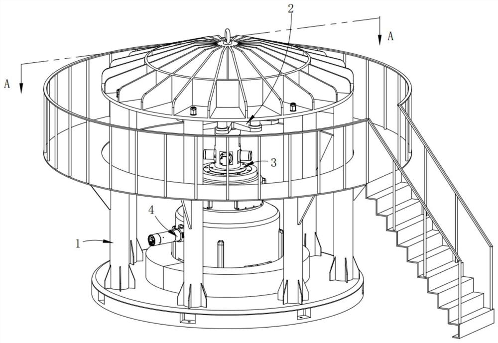
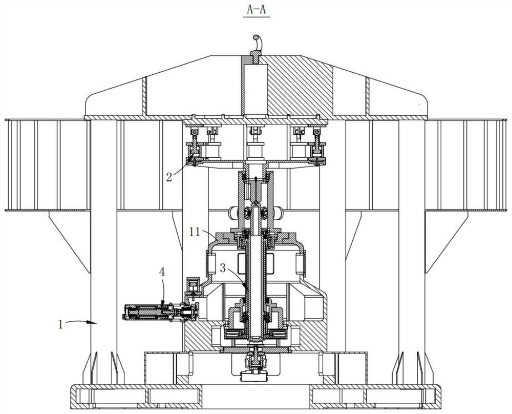
[0083] Such as Figure 1-3 As shown, the supporting bearing test machine for the helicopter rotor system includes:

[0084] A frame 1, the frame 1 is provided with a host casing 11;

[0085] loading system 2, the loading system 2 is arranged under the top of the frame 1; and

[0086] Dual-rotor system 3, described dual-rotor system 3 is arranged in described main frame housing 11 and is connected with the output end of the loading force of described loading system 2;

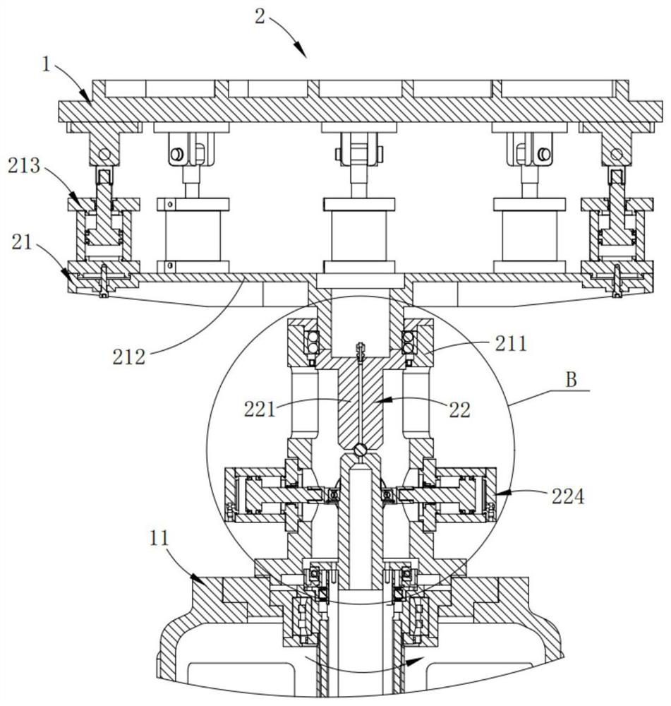
[0087] The loading system 2 includes:

[0088] A propeller simulation system 21, the upper end of the propeller simulation system 21 is connected to the top of the frame 1; and

[0089] A floating system 22, the upper end of the floating system 22 is connected to the propeller simulation system 21 in a floating manner, and the lower end thereof is connected to the dual-rotor system 3;

[0090] The propeller simulation system 21 simulates different flight states of the helicopter, such as vertical motion, pit...

Embodiment 2

[0116] Such as Figure 9-14 As shown, the parts that are the same as or corresponding to those in the first embodiment are identified with reference numerals corresponding to the first embodiment. For the sake of simplicity, only the differences from the first embodiment will be described below. The difference between this embodiment two and embodiment one is:

[0117] In this example, if Figure 9-11 As shown, the dual-rotor system 3 includes:

[0118] Upper transition assembly 31, described upper transition assembly 31 is connected with the top of described host housing 11;

[0119] Lower transition assembly 32, described lower transition assembly 32 is connected with the below of described host housing 11;

[0120] Hollow outer rotor shaft 33, the upper end of the hollow outer rotor shaft 33 is connected to the connecting seat 313 of the upper transition assembly 31, the lower end of the hollow outer rotor shaft 33 and the lower transition assembly 32 pass through the fi...

Embodiment 3

[0146] Such as Figure 15-16 As shown, the parts that are the same as or corresponding to those in the first embodiment are identified with reference numerals corresponding to the first embodiment. For the sake of simplicity, only the differences from the first embodiment will be described below. The difference between this embodiment three and embodiment one is:

[0147] In this embodiment, the testing machine also includes an input end bearing test system 4, which is arranged on the main machine housing 11 and is used for performance testing the sixth test bearing 106 installed at the input end. ; The input end bearing testing system 4 includes:

[0148] An input power unit 41, the input power unit 41 is arranged on one side of the main engine casing 11;

[0149] Bearing installation unit 42, described bearing installation unit 42 is connected with the output end of described input power unit 41 by plum blossom elastic coupling and is arranged on the main engine casing 11;...


PUM


Abstract

The invention provides a helicopter rotor system matched bearing testing machine. The helicopter rotor system matched bearing testing machine comprises a loading system; and a dual-rotor system, wherein the dual-rotor system comprises a hollow outer rotor shaft; an inner rotor shaft and a power unit; different flight states of a helicopter are simulated through the propeller simulation system, so forces in different stress states are transmitted to the double-rotor system provided with the to-be-tested bearing pack through the floating pendulum system, and then performance test of the to-be-tested bearing pack is realized; by utilizing a floating steel ball in the floating pendulum system, the force is stably and smoothly transmitted to the to-be-tested bearing pack in the force transmission process, so the bearing performance test is carried out under the real working condition; an input end bearing test system arranged on one side of the rack is utilized to realize synchronous test of the rotor bearing and the input end bearing, so test efficiency is improved.

Description

technical field [0001] The invention relates to the technical field of bearing testing, in particular to a testing machine and method for a supporting bearing of a helicopter rotor system. Background technique [0002] Coaxial dual-rotor helicopter refers to the upper and lower rotors with one forward and one reverse rotation around the same theoretical axis. Due to the opposite steering, the torque generated by the two rotors is controlled in a flight with a constant heading. , which are mutually balanced in the state, and the unbalanced torque generated by the differential of the upper and lower rotor collective pitches can realize that the heading is a lifting surface and a vertical, horizontal and heading control surface. [0003] Chinese patent CN 105136459 B discloses a kind of swing oil cylinder type helicopter tail rotor system supporting combined joint bearing testing machine. The servo-driven oil cylinder of the testing machine is fixed on the upper platform throu...

Claims


Application Information

Patent Timeline
Patent Type & Authority Applications(China)
IPC IPC(8): G01M13/04B64F5/60
CPCG01M13/04B64F5/60
Inventor 陈仁波张佩思姜艳红郭帅雷鸣浩徐俊
Owner 中浙高铁轴承有限公司
Why Eureka
Try Eureka