Method for correcting external parameters of laser radar in unmanned driving

A laser radar and unmanned driving technology, applied in the field of data processing, can solve low-level problems, reduce the correction time, improve the correction effect, and save the correction cost.

Inactive Publication Date: 2021-10-26
BEIJING QINGZHOUZHIHANG TECH CO LTD
View PDF0 Cites 7 Cited by
  • Summary
  • Abstract
  • Description
  • Claims
  • Application Information

AI Technical Summary

Problems solved by technology

[0003] The purpose of the present invention is to address the defects of the prior art, to provide a correction method, electronic equipment and computer-readable storage medium for the external parameters of the laser radar in unmanned driving, so as to ensure that there is a calibrated standard laser radar on the vehicle, so as to This standard lidar is used as a benchmark to estimate the pose conversion matrix from radar to radar for other vehicle-mounted lidars, and use the better convergence constraint estimation matrix to perform secondary corrections on the pose conversion matrix estimated under conventional road conditions. Combining the corrected radar-to-radar pose transformation matrix with the pose transformation matrix from the standard laser radar to the vehicle coordinate system, the latest corrected external parameters of other vehicle-mounted laser radars can be obtained; The problem of low correction efficiency caused by networking requirements, specified location requirements, etc. can also be adjusted without re-commissioning based on the coordination relationship between radars after the correction is completed, which can save correction costs, reduce correction time, and improve correction effects.

Method used


Image

  • Method for correcting external parameters of laser radar in unmanned driving
  • Method for correcting external parameters of laser radar in unmanned driving

Examples


Embodiment Construction

[0033] In order to make the object, technical solution and advantages of the present invention clearer, the present invention will be further described in detail below in conjunction with the accompanying drawings. Obviously, the described embodiments are only some embodiments of the present invention, rather than all embodiments . Based on the embodiments of the present invention, all other embodiments obtained by persons of ordinary skill in the art without making creative efforts belong to the protection scope of the present invention.

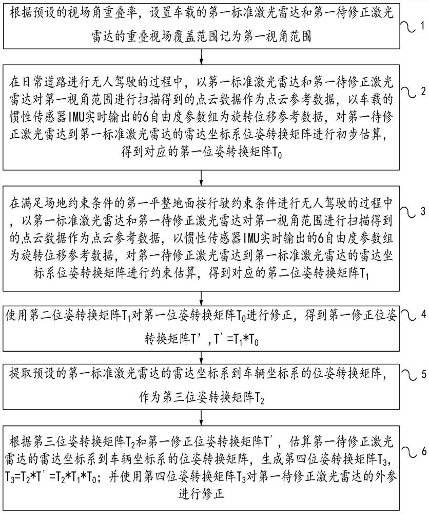
[0034] When the vehicle wants to correct the external parameters of the laser radar of its own vehicle, a standard laser radar that has been calibrated is installed on the vehicle in advance, and then through the correction of the external parameters of the laser radar in unmanned driving provided by Embodiment 1 of the present invention Method, use the standard lidar to be corrected lidar on the daily road to conduct a preliminary estimati...


PUM


Abstract

The embodiment of the invention relates to a method for correcting external parameters of a laser radar in unmanned driving. The method comprises the steps of setting a first standard laser radar, and recording the coverage range of an overlapped view field of the to-be-corrected laser radar as a first view angle range, performing preliminary estimation on a pose conversion matrix from the first to-be-corrected laser radar to the first standard laser radar on a daily road to obtain a first pose conversion matrix T0, performing constraint estimation on the first to-be-corrected laser radar to first standard laser radar pose conversion matrix on the first flat ground to obtain a second pose conversion matrix T1, correcting the first pose conversion matrix T0 to obtain a first corrected pose conversion matrix T', extracting a third pose conversion matrix T2, estimating a pose conversion matrix of the first to-be-corrected laser radar to generate a fourth pose conversion matrix T3, and correcting the external parameters of the first to-be-corrected laser radar. Through the method, the correction cost can be saved, the correction time is shortened, and the correction effect is improved.

Description

technical field [0001] The invention relates to the technical field of data processing, in particular to a method for correcting external parameters of laser radar in unmanned driving. Background technique [0002] Multiple lidars are usually installed in an unmanned driving system. Due to installation errors, replacement of radar failures, deformation of mounting brackets, etc., it is usually necessary to correct one or several of the lidar external parameters. The conventional correction method is to use the prior map data to estimate the pose transformation matrix of the point cloud data generated by each radar scan according to the principle of position alignment, and use the estimated pose transformation matrix as the corrected external parameter to set the radar . Because this mode of operation requires the cooperation of background map data, it has relatively high requirements on the network. In order to achieve a better correction effect, it is often necessary to g...

Claims


Application Information

Patent Timeline
Patent Type & Authority Applications(China)
IPC IPC(8): G01S7/497G01S17/931
CPCG01S7/497G01S17/931
Inventor 陈东张雨
Owner BEIJING QINGZHOUZHIHANG TECH CO LTD
Why Eureka
Try Eureka