
Two-stage-separation dust removal equipment and method thereof

A dust removal equipment and stage separation technology, applied in the field of two-stage separation dust removal equipment, can solve the problems of difficult separation of fine particles, high resistance of dust removal equipment, high energy consumption, etc., achieve effective recovery, reduce pressure drop loss, and increase separation efficiency Effect

Active Publication Date: 2021-10-29
NANJING UNIV OF AERONAUTICS & ASTRONAUTICS
View PDF7 Cites 1 Cited by
  • Summary
  • Abstract
  • Description
  • Claims
  • Application Information

AI Technical Summary

Problems solved by technology

[0004] The object of the present invention is to provide a kind of low-resistance, high-efficiency and can be applicable to a kind of two-stage separation dedusting equipment and its method of particles of a wider range of particle sizes, its advantage is to solve the traditional cyclone separator due to the opposite direction of internal and external swirling The resulting pressure drop is too large and it is difficult to separate fine particles, so that the dust removal equipment is no longer limited by particle size, replacing common methods such as filter screens and electrostatic dust removal, and eliminating the shortcomings of high resistance and high energy consumption of dust removal equipment. , while improving the performance of the existing cyclone separator, with excellent universality

Method used


Image

  • Two-stage-separation dust removal equipment and method thereof
  • Two-stage-separation dust removal equipment and method thereof
  • Two-stage-separation dust removal equipment and method thereof

Examples


Embodiment Construction

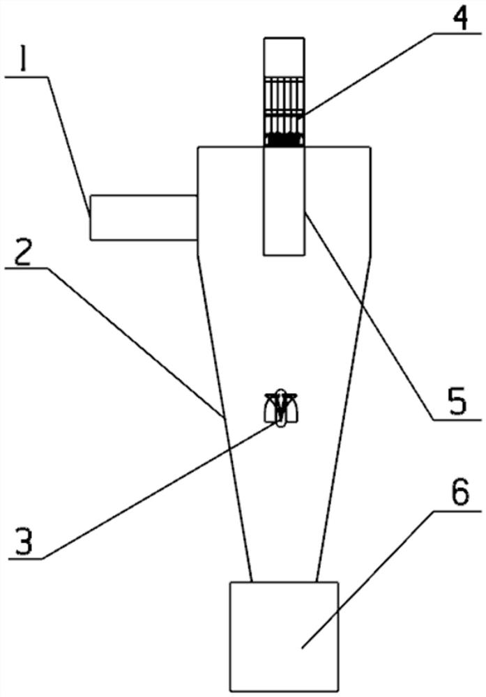
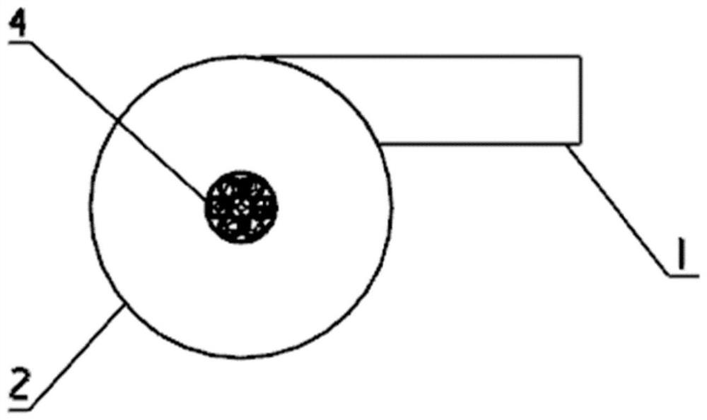
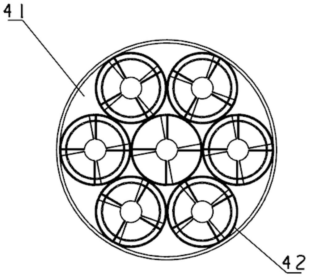
[0030] In order to make those skilled in the art understand the technical scheme of the present invention, below in conjunction with Figure 1-5 Do as follows.

[0031] A two-stage separation dedusting device and its method, comprising: a side air intake cylinder 1, a cyclone cylinder 2, a deflector 3, an array type swirl pipe 4, an internal exhaust pipe 5, and a dust collector 6; wherein, the array type The swirl tube 4 includes an outer cylinder 41 and a swirl tube unit 42 ; the swirl tube unit 42 includes a barrel unit 421 , a swirl sub-unit 422 , and a tail nozzle unit 423 .

[0032] The fluid that needs to be separated enters the side air inlet cylinder 1, and because the side air inlet cylinder 1 is tangent to the cyclone 2, the fluid produces high-speed rotational motion, most of the fluid flows in a spiral form around the inner wall of the side cyclone 2, and a small part The fluid moves downward around the inner exhaust pipe 5;

[0033] Most of the fluid flow starts...


PUM


Abstract

The invention discloses two-stage-separation dust removal equipment and a method thereof, belonging to the field of industrial dust removal. The equipment sequentially comprises an array type cyclone pipe, a cyclone cylinder and a dust collector from top to bottom, wherein the array type cyclone pipe comprises an outer cylinder and a plurality of cyclone pipe units embedded into the outer cylinder in an array mode; each cyclone pipe unit comprises a barrel unit, a cyclone subunit and an exhaust nozzle unit; and an inner exhaust pipe and a flow guide piece are sequentially arranged in the cyclone cylinder from top to bottom along a central axis, the lower end of the cyclone cylinder is connected with the dust collector, and the inner exhaust pipe is arranged at the inner upper end of the cyclone cylinder along the central axis. According to the invention, by adding the flow guide piece and an array type cyclone pipe structure, the rotating direction of cyclone in a cyclone separator is adjusted, secondary separation is carried out on inner cyclone, pressure drop loss is reduced, and separation efficiency is improved.

Description

technical field [0001] The invention designs a two-stage separation dedusting device and a method thereof, belonging to the field of industrial dedusting. Background technique [0002] In industrial production, it is necessary to effectively remove mixed dust and sand particles from the air or sewage in time to avoid particle accumulation and improve the service life of equipment. Therefore, separation technology is widely used in coal combustion, mining, mechanical processing, material processing, chemical industry, food and other fields. Because of its simple operation, convenient management, low price and high separation efficiency, the cyclone separator is widely used in the separation of gas-solid or liquid-solid systems, especially suitable for fields with high dust concentration and large particle size. [0003] However, the separation efficiency of the cyclone separator for fine dust is low, resulting in the escape of fine dust. At present, the measures taken to sol...

Claims


Application Information

Patent Timeline
Patent Type & Authority Applications(China)
IPC IPC(8): B01D45/04B01D45/16B04C5/04B04C5/24B04C5/10
CPCB01D45/04B01D45/16B04C5/04B04C5/24B04C5/103
Inventor 朱德志韩东何纬峰纪妍妍彭伟杰
Owner NANJING UNIV OF AERONAUTICS & ASTRONAUTICS
Learn More