
Bidirectional ultrasonic automatic tool changing motorized spindle

A technology of automatic tool change and electric spindle, applied in the direction of fluid using vibration, large fixed members, metal processing machinery parts, etc. and other problems to achieve the effect of large installation redundancy

Active Publication Date: 2021-10-29
常州捷乾机电科技有限公司
View PDF9 Cites 0 Cited by
  • Summary
  • Abstract
  • Description
  • Claims
  • Application Information

AI Technical Summary

Problems solved by technology

[0002] In the current high-end manufacturing, the cutting of superhard materials is a big problem. The main reason is that the electric spindles currently used for cutting are all high-speed rotating types, and it is difficult to process superhard materials.
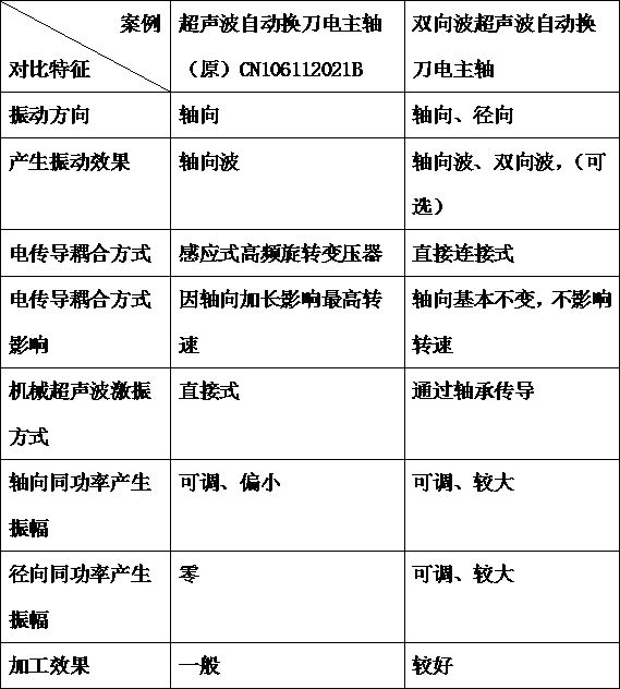
[0003] The existing ultrasonic automatic tool-changing electric spindle, such as the ultrasonic automatic tool-changing electric spindle disclosed in patent number CN106112021B, adopts the axial vibration mode, which generates axial waves, and cannot process superhard materials

Method used


Image

  • Bidirectional ultrasonic automatic tool changing motorized spindle
  • Bidirectional ultrasonic automatic tool changing motorized spindle
  • Bidirectional ultrasonic automatic tool changing motorized spindle

Examples


Embodiment Construction

[0021] The preferred embodiments of the present invention will be described in detail below in conjunction with the accompanying drawings, so that the advantages and features of the present invention can be more easily understood by those skilled in the art, so as to define the protection scope of the present invention more clearly. The directional terms mentioned in the present invention, such as "up", "down", "front", "back", "left", "right", "top", "bottom", etc., are only for reference to the attached drawings. direction. Therefore, the directional terms used are used to illustrate and understand the present invention, but not to limit the present invention.

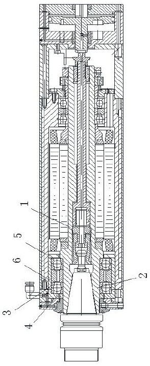
[0022] like figure 1 A two-way wave ultrasonic automatic tool change electric spindle shown includes a main body of the electric main shaft and a rotor shaft 1 arranged in the main body of the electric main shaft. The rotor shaft 1 realizes rotation with the main body of the electric main shaft through a bearing 3 ....


PUM


Abstract

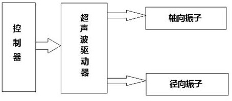
The invention relates to a bidirectional ultrasonic automatic tool changing motorized spindle which comprises a motorized spindle body and a rotor shaft. The rotor shaft penetrates through an inner ring of a bearing to achieve rotation, an axial vibrator and a radial vibrator are installed at the position of a tool bit of the rotor shaft, and the axial vibrator and the radial vibrator are arranged on the outer end face of the bearing in a sleeving manner; and the axial vibrator and the radial vibrator are connected with an ultrasonic driver, the axial vibrator can axially excite the bearing, the radial vibrator can radially excite the bearing, the bearing is sleeved with an elastic deformation pad, and the two ends of the elastic deformation pad abut against the axial vibrator and the radial vibrator correspondingly. By means of the bidirectional ultrasonic automatic tool changing motorized spindle, an axial and radial vibration superposition method is adopted, a rotary tool bit is subjected to excitation, excitation can be conducted in the same frequency and in the same phase or in the same frequency and in different phases or alternately according to the cutting effect, finally, the rotor shaft vibrates in the axial direction and also vibrates in the radial direction, and bidirectional vibration is formed. The bidirectional ultrasonic automatic tool changing motorized spindle is easy to install, firm in structure, stable in work and capable of achieving axial and radial cutting.

Description

technical field [0001] The invention relates to the technical field of electric spindles, in particular to a two-way wave ultrasonic automatic tool-changing electric spindle for cutting superhard materials. Background technique [0002] In the current high-end manufacturing, the cutting of superhard materials is a major problem. The main reason is that the electric spindles currently used for cutting are all high-speed rotating types, which makes it difficult to process superhard materials. [0003] The existing ultrasonic automatic tool-changing electric spindle, such as the ultrasonic automatic tool-changing electric spindle disclosed in Patent No. CN106112021B, adopts an axial vibration mode, which generates axial waves, and cannot process superhard materials. Contents of the invention [0004] As we all know, the cutting of superhard materials is a major problem in the processing industry. The present invention is mainly designed to solve the problem of cutting superha...

Claims


Application Information

Patent Timeline
IPC IPC(8): B23B19/02B06B1/06
CPCB23Q1/70B06B1/06
Inventor 张洁张建生钱程赵鹏飞陈骏
Owner 常州捷乾机电科技有限公司
Learn More