Welding device for engineering machine parts

A welding device and engineering machinery technology, applied in auxiliary devices, welding equipment, auxiliary welding equipment, etc., can solve problems such as economic loss, easy loss, and impact on work efficiency.

Inactive Publication Date: 2021-10-29
HARBIN VOCATIONAL & TECHN COLLEGE
View PDF0 Cites 0 Cited by
  • Summary
  • Abstract
  • Description
  • Claims
  • Application Information

AI Technical Summary

Problems solved by technology

[0002] In the welding process of construction machinery, due to the large number of parts and components, there are a large number of manual welding parts. Manual welding requires a large number of electrodes. There are many probl

Method used


Image

  • Welding device for engineering machine parts
  • Welding device for engineering machine parts
  • Welding device for engineering machine parts

Examples


Embodiment Construction

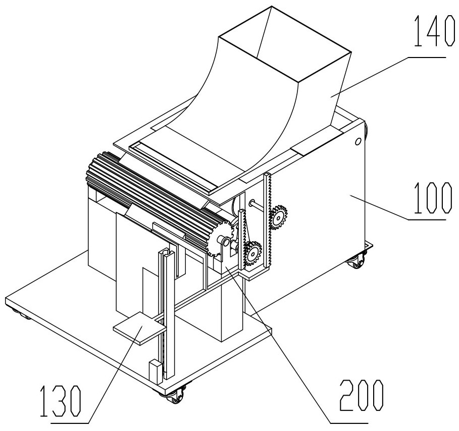
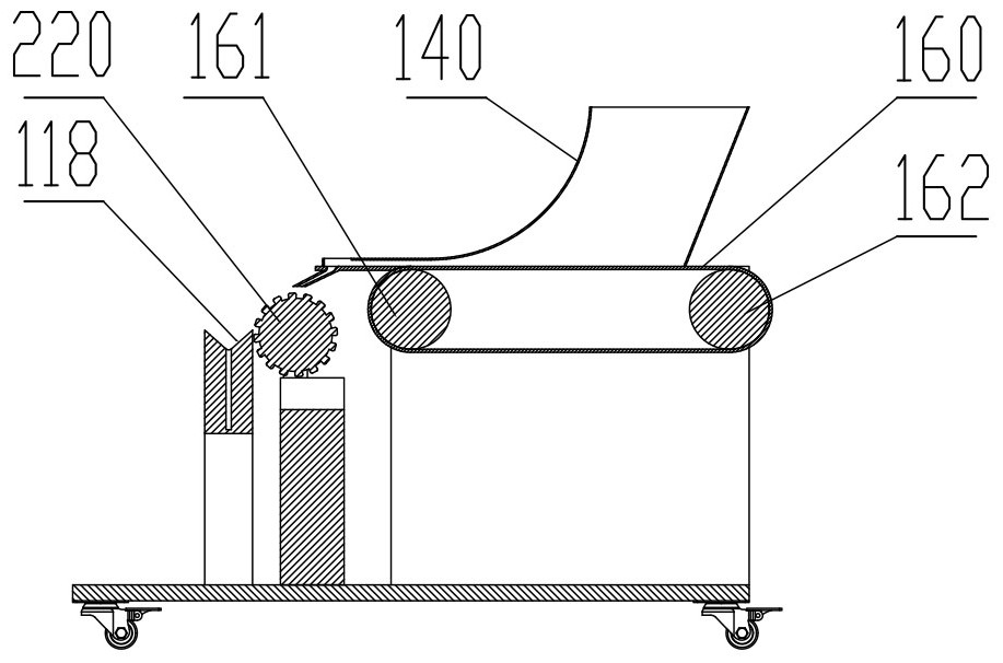
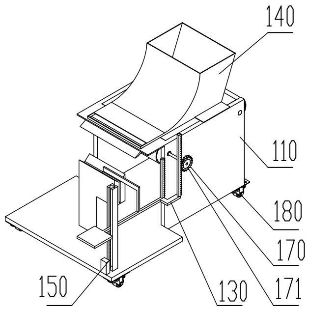
[0022] Below according to accompanying drawing and embodiment the present invention will be described in further detail:

[0023] A welding device for construction machinery parts, including a body device 100, a material shifting device 200, the body device 100 includes a frame 110, a pedal 130, a hopper 140, a spring 150, a belt 160, a front roller 161, a rear roller 162, a No. Gear 170, No. 1 one-way bearing 171, material shifting device 200 includes material shifting rack 210, material shifting roller 220, cam 230, roller 240, pawl frame 250, pawl 260, No. 2 gear 270, No. 2 one-way bearing 271, the material shifting device 200 is fixedly connected to the front of the frame 110; the rear side of the frame 110 has a left-right symmetrical vertical plate 111, and the rear side of the vertical plate 111 has a rear roller hole 112, and the rear roller hole 112 runs through two vertical Plate 111, the front side of the rear roller hole 112 has a front roller hole 113, the front r...


PUM


Abstract

A welding device for engineering machine parts comprises a machine body device and a material stirring device. The machine body device comprises a rack, a pedal, a hopper, a spring, a belt, a front roller, a rear roller, a first gear and a first one-way bearing. The material stirring device comprises a material stirring frame, a material stirring roller, a cam, a rolling wheel, a pawl frame, a pawl, a second gear and a second one-way bearing, and the material shifting device is fixedly connected with the front portion of the rack. Vertical plates in bilateral symmetry are arranged on the rear side of the rack, rear roller holes are formed in the rear sides of the vertical plates and penetrate through the two vertical plates, front roller holes are formed in the front sides of the rear roller holes and penetrate through the two vertical plates, a front plate is arranged on the front sides of the vertical plates, a discharging groove is formed in the lower portion of the front plate, a receiving frame is arranged in the middle of the rack, a hopper opening is formed in the upper portion of the receiving frame, a clamping groove is formed in the right side of the hopper opening, a stand column is arranged on the front side of the rack, and a guide hole is formed in the middle of the stand column.

Description

technical field [0001] The invention relates to the field of welding, in particular to a welding device for parts of engineering machinery. Background technique [0002] In the welding process of construction machinery, due to the large number of parts and components, there are a large number of manual welding parts. Manual welding requires a large number of electrodes. There are many problems in the storage and retrieval of electrodes on site. If it is placed on site, it is not easy to find, and it is easy to lose. It takes time and effort to get the welding rod, which affects work efficiency and causes economic losses. Contents of the invention [0003] The present invention aims at the above-mentioned deficiencies in the prior art, and provides a welding device for parts of construction machinery. [0004] The purpose of the present invention is to realize through the following technical solutions: [0005] A welding device for construction machinery parts, including ...

Claims


Application Information

Patent Timeline
IPC IPC(8): B23K37/00
CPCB23K37/00
Inventor 赵丹金显吉阎巍山雍丽英刘万村谢吉龙陈秀赵邵松
Owner HARBIN VOCATIONAL & TECHN COLLEGE
Why Eureka
Try Eureka