Automatic screw turning device for product assembly

A technology for screwing and screwing, which is applied in the field of automatic screwing devices for product assembly, which can solve the problems of low screwing efficiency and achieve the effects of improving work efficiency, reducing vibration feeding devices, and compact production lines

Active Publication Date: 2021-10-29
江苏墨新电子科技有限公司
View PDF11 Cites 0 Cited by
  • Summary
  • Abstract
  • Description
  • Claims
  • Application Information

AI Technical Summary

Problems solved by technology

[0005] The purpose of the present invention is to overcome the inefficiency of screw screwing in existing product assembly, and provide an automatic screw screw device for product assembly. By adopting the technical solution of the present invention, the product conveying device is used to intermittently transport the products to be screwed, and at the same time cooperate with at least two A set of multi-station screwing devices, and each group of multi-station screwing devices has at least two sets of screwing mechanisms, the screwing mechanisms on each multi-station screwing device correspond to screw holes in different positions on the product, and mutually The staggered distribution provides enough space for the installation of the existing electric screwdriver, and realizes the simultaneous automatic screwing and assembly of multiple screws on the product on a short production line, greatly improving the work efficiency of screwing on the product, and The production line is more compact and saves space. At the same time, the use of screw arrangement and ejection mechanism further reduces the vibration feeding device, making the arrangement of each group of multi-station screwing devices more compact, and the screwing action is more efficient and stable.

Method used


Image

  • Automatic screw turning device for product assembly
  • Automatic screw turning device for product assembly
  • Automatic screw turning device for product assembly

Examples


Embodiment

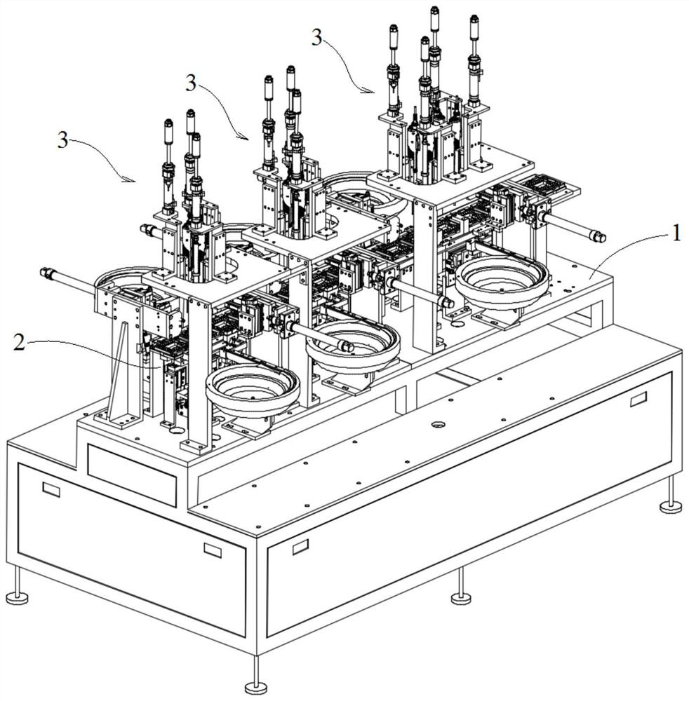
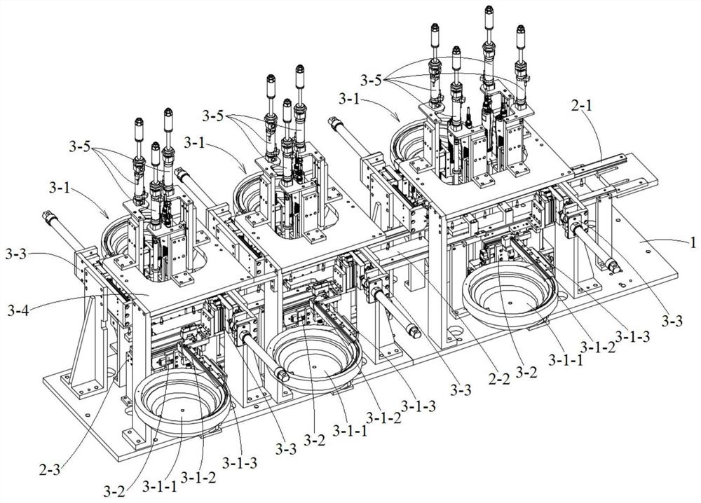
[0038] to combine figure 2 and image 3 As shown, an automatic screw screwing device for product assembly in this embodiment includes a workbench 1, a product delivery device 2 installed on the workbench 1 for driving the intermittent movement of the product to be screwed, and at least Two sets of multi-station screwing devices 3, the multi-station screwing devices 3 are arranged sequentially along the product conveying device 2, and the positions of the screw holes on the corresponding products of each multi-station screwing device 3 are staggered from each other, and the products are arranged along the product conveying device 2 Circulation, the screw loading positioning and screwing are carried out at each multi-station screwing device 3 in turn, realizing the automatic screwing assembly of multiple screws on a product. in,

[0039] Such as image 3 , Figure 6 to Figure 9 As shown, the above-mentioned multi-station screwing device 3 includes a screw feeding mechanism ...


PUM


Abstract

The invention discloses an automatic screw turning device for product assembly, and belongs to the field of automatic assembly equipment. According to the automatic screw turning device for product assembly, a product conveying device is used for intermittently conveying products with screws to be turned, meanwhile, at least two multi-station screw turning devices are matched, and each multi-station screw turning device is provided with at least two screw screwing mechanisms; and the screw screwing mechanisms on the multi-station screw turning devices correspond to screw holes in different positions of the products and are distributed in a staggered mode, enough space is provided for installation of an existing electric screwdriver, a plurality of screws on the products can be automatically screwed and assembled at the same time on a short production line, the working efficiency of turning the screws on products is greatly improved, the production line is more compact, the space is saved, meanwhile, vibration feeding devices are further reduced through a screw arranging and ejecting mechanism, the arrangement of all the multi-station screw turning devices is more compact, and the screw turning action is more efficient and stable.

Description

technical field [0001] The present invention relates to a kind of product assembly equipment, more specifically, relates to an automatic screwing device for product assembly. Background technique [0002] figure 1 It is a schematic diagram of an assembly structure of an existing electronic product, which includes a plastic base 100 and a circuit board 200, the circuit board 200 is assembled on the plastic base 100, and the two are fixed by screws. Such as figure 1 As shown, there are 10 screw holes 300 between the plastic base 100 and the circuit board 200 , and screws need to be screwed into the 10 screw holes 300 for fixing. Since the distances between the screw holes 300 are very close, it is very difficult to automatically screw the screws. At present, the screws are manually screwed, the assembly efficiency is very low, the labor intensity is very high, and there are problems such as missing or not tightening the screws. [0003] figure 1 There are still many such ...

Claims


Application Information

Patent Timeline
Patent Type & Authority Applications(China)
IPC IPC(8): B23P19/06
CPCB23P19/069B23P19/001B23P19/004B23P19/007
Inventor 包旻强朱加正
Owner 江苏墨新电子科技有限公司
Why Eureka
Try Eureka