
Miniature linear machining center based on electromagnetic clutch principle and using method

A machining center and electromagnetic clutch technology, applied in the direction of manufacturing tools, other manufacturing equipment/tools, etc., to prevent the tool holder from falling off, ensure stability, and simplify the mechanical structure

Active Publication Date: 2021-10-29
徐州清歌机械制造有限公司
View PDF9 Cites 4 Cited by
  • Summary
  • Abstract
  • Description
  • Claims
  • Application Information

AI Technical Summary

Problems solved by technology

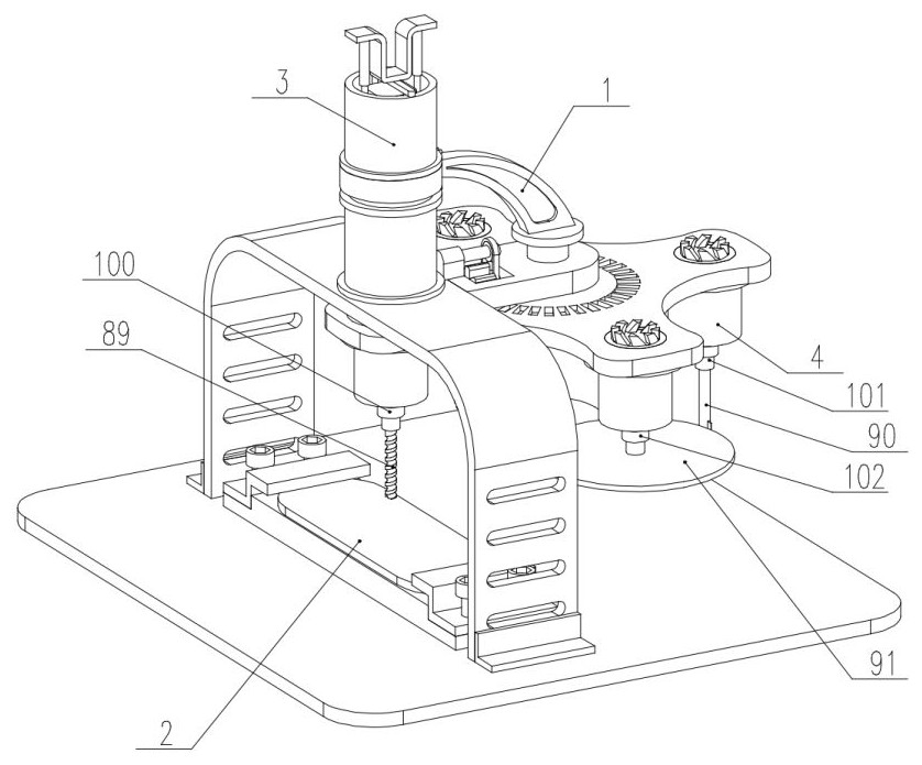
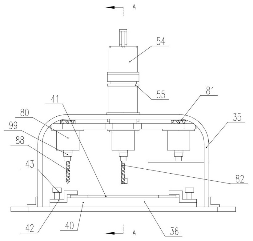
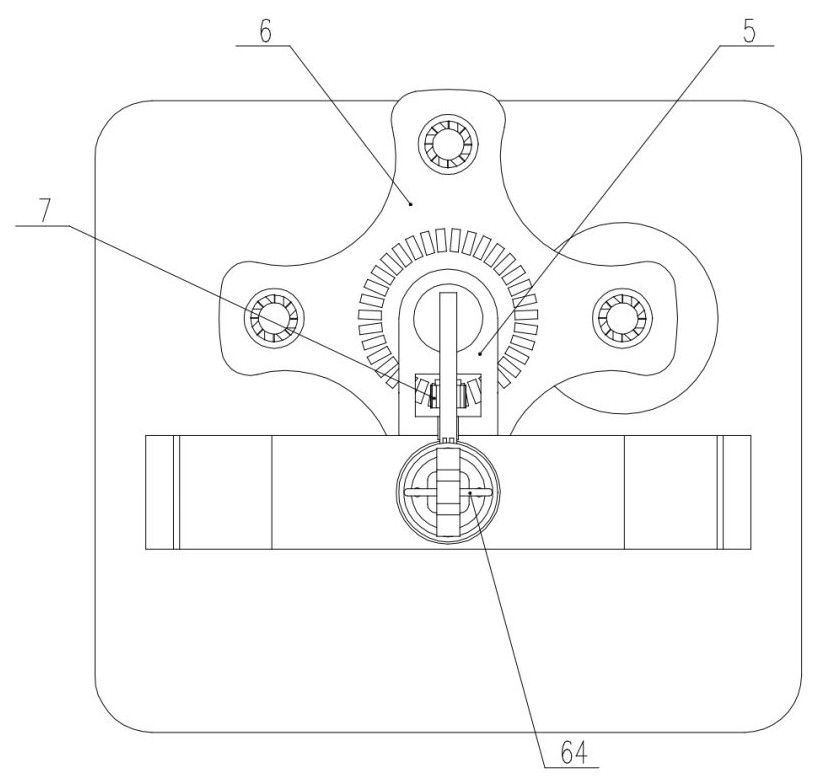
[0008] In view of the above situation, in order to overcome the defects of the prior art, the present invention provides a miniature linear machining center based on the principle of electromagnetic clutch and its use method. In the step of tool change, the principle of electromagnetic clutch is creatively used to simplify the complexity. A large number of complicated transmission structures are omitted, which reduces the mechanical failure rate. The electromagnetic clutch has the advantages of simple structure, large driving force, and fast response speed, and can quickly drive the tool magazine to move between the top and bottom limit positions; the tool magazine part uses planetary The structure, the tool is replaced by the revolution of the tool magazine itself. After the tool holder and the drive unit are connected, they can rotate and lift under the guidance of the tool magazine. Generally, the parts that are connected by longitudinal movement will be connected with each other by straight teeth, and Cooperate with the locking mechanism to prevent it from falling off. The invention creatively uses inclined transmission teeth with a large upper part and a smaller lower part, which can not only transmit torque when rotating, but also have a self-locking function. In the case of omitting a whole set of locking mechanisms It can still prevent the tool holder from falling off and ensure the stability of power transmission. When driving the tool magazine to rotate, it is different from the commonly used steel gears. The present invention uses PA materials to make gears. Because PA materials have high strength, The characteristic of high toughness, through the small amount of deformation of the square tooth itself, compensates the angle deviation between the tooth and the tooth groove, which greatly reduces the processing difficulty and processing requirements of the tooth groove, and reduces the cost; the general fixture of the general machining center needs to be obtained from multiple The position squeezes the workpiece from top to bottom to prevent the workpiece from shifting during processing. In order to further simplify the structure, optimize the operation process and space layout, the present invention creatively uses pressure-sensitive adhesive as the connecting material, and the pressure-sensitive adhesive can be bonded The smooth metal surface can quickly increase the viscosity when the pressure is applied, and it can be easily removed from the object after the pressure is removed. It is pollution-free and can be used repeatedly. When using it, you only need to press the part from the opposite corner. There will be no slippage in the horizontal direction

Method used


Image

  • Miniature linear machining center based on electromagnetic clutch principle and using method
  • Miniature linear machining center based on electromagnetic clutch principle and using method
  • Miniature linear machining center based on electromagnetic clutch principle and using method

Examples


Embodiment Construction

[0039] The technical solutions in the embodiments of the present invention will be clearly and completely described below in conjunction with the accompanying drawings in the embodiments of the present invention. Obviously, the described embodiments are only some of the embodiments of the present invention, not all of them; based on The embodiments of the present invention and all other embodiments obtained by persons of ordinary skill in the art without making creative efforts belong to the protection scope of the present invention.

[0040] In describing the present invention, it should be understood that the terms "upper", "lower", "front", "rear", "left", "right", "top", "bottom", "inner", " "Outside" and other indication orientations or positional relationships are based on the orientations or positional relationships shown in the drawings, and are only for the convenience of describing the present invention and simplifying the description, rather than indicating or implyi...


PUM


Abstract

The invention discloses a miniature linear machining center based on an electromagnetic clutch principle and a using method thereof. The miniature linear machining center comprises an electromagnetic clutch type tool changing locking mechanism, a pressure bonding type anti-falling positioning base, an integrated protection type lifting driving sleeve and an elastic telescopic tool fixing transmission mechanism. The invention belongs to the technical field of integrated machining, and particularly relates to the miniature linear machining center based on the electromagnetic clutch principle and the using method. The position of a tool rest is fixed through an electromagnetic clutch structure, and the relative fixing strength of a workpiece and the base is improved through the base based on pressure-sensitive adhesive under the condition that excessive limiting structures do not exist; and the tool changing action is conducted through the tool capable of elastically stretching out and drawing back, and the problems that a small integrated machining center in the current market is complex in structure, low in integration level, high in maintenance difficulty, tedious in operation step and the like are effectively solved.

Description

technical field [0001] The invention belongs to the technical field of integrated machining, and specifically refers to a miniature linear machining center based on the principle of electromagnetic clutch and a method for using it. Background technique [0002] Machining center generally refers to a highly integrated multifunctional machine tool with tool magazine and automatic tool changer. The general machining center has complete functions and can perform almost all common machining operations; but this kind of machining center is large in size, The structure is complicated, the price is expensive, and the cost of learning and use is high. For users who specialize in the production of a certain subcategory of products, a small machining center with some functions is often a more cost-effective choice; for example, it specializes in casting For the manufacturers of simple processes such as single-point drilling, boring, finishing or surface grinding of completed small flan...

Claims


Application Information

Patent Timeline
Patent Type & Authority Applications(China)
IPC IPC(8): B23P23/04
CPCB23P23/04
Inventor 彭照成
Owner 徐州清歌机械制造有限公司
Learn More