
Cloth dyeing mechanism for textile production

A fabric and feeding tube technology, applied in textile processing machine accessories, textile material processing, textile material carrier processing, etc., can solve the problems of unstable chemical concentration in pad dyeing tank, different dye liquor concentration, high additive concentration, etc. To achieve the effect of speeding up the mixing of dye liquor

Active Publication Date: 2021-10-29
九江市骏昇纺织科技有限公司
View PDF7 Cites 0 Cited by
  • Summary
  • Abstract
  • Description
  • Claims
  • Application Information

AI Technical Summary

Problems solved by technology

[0003] In the process of cold-batch dyeing, the most common problem is that the concentration of chemicals in the pad dyeing tank is unstable. After padding a certain length of fabric, the chemical weight gain rate on the fabric decreases significantly, resulting in the loss of dyed and finished fabrics. Performance or color depth is reduced. In order to obtain a constant pad dyeing tank concentration and chemical weight gain rate, a lower initial concentration and a higher added concentration must be used. In the prior art, the high-concentration dye solution is directly added to the In the rolling tank, there is no mixing process between the newly added dye solution and the dye solution, which will still cause the concentration of the dye solution to be different, resulting in color difference

Method used


Image

  • Cloth dyeing mechanism for textile production
  • Cloth dyeing mechanism for textile production
  • Cloth dyeing mechanism for textile production

Examples


Embodiment

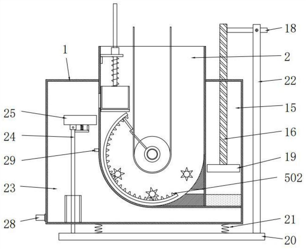
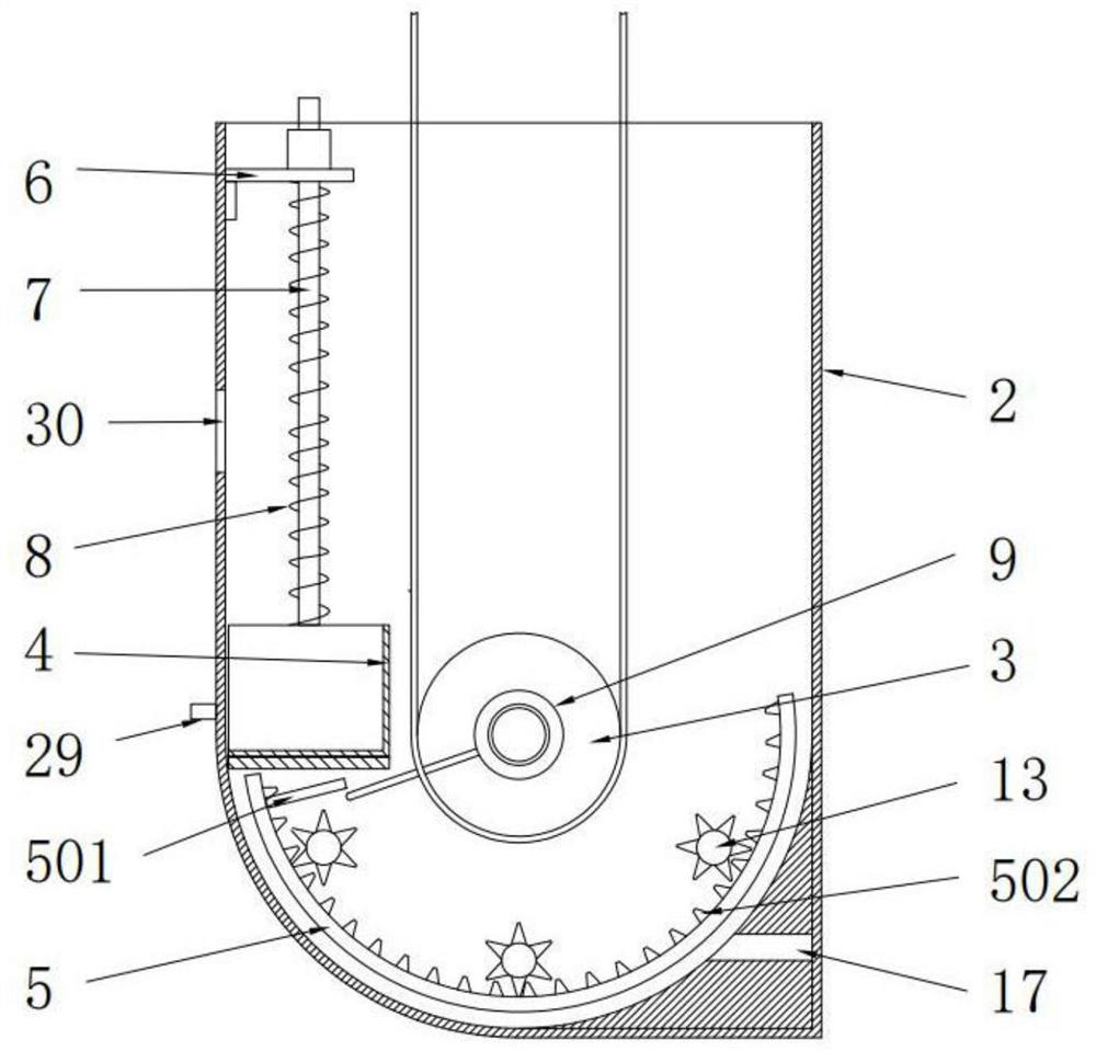
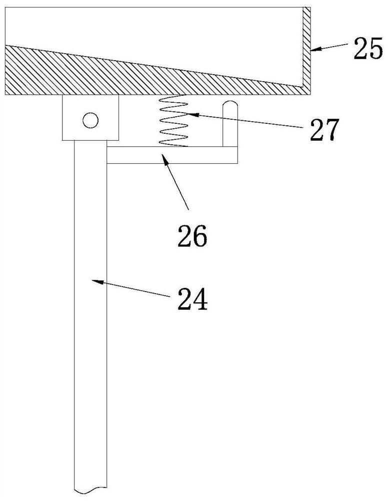
[0029] See Figure 1-5 A fabric staining mechanism for textile production, including the outer casing 1, the upper side of the outer casing 1, and the bottom end of the soaking groove 2 is u-shaped, and the inside of the immersion groove 2 is provided with a guide roller 3. , Movable seat 4, movable plate 5 and fixed plate 6;

[0030] The fixing plate 6 is disposed on the upper end of the immersion groove 2, and the movable seat 4 is located on the lower side of the fixing plate 6, and the upper end of the movable seat 4 is provided with a guide bar 7, the position and the number of the guide rod 7 corresponds to the fixed plate 6. And the guide rod 7 is slidked on the fixing plate 6, and the movable seat 4 is also elastically coupled to the fixing plate 6 by the connecting spring 8, and the fixing plate 6 is in shape, and one end of the fixing plate 6 is fixed to the immersion groove 2, the movable seat 4 is a rectangular shape, and the top of the movable seat 4 is an open structu...


PUM


Abstract

The invention relates to the technical field of cloth dyeing, and discloses a cloth dyeing mechanism for textile production. The cloth dyeing mechanism comprises a shell; the upper side of the shell is provided with a padding groove; the bottom end of the padding groove is U-shaped; the inner side of the padding groove is provided with a cloth guide roller, a movable seat, a movable plate and a fixed plate; the fixed plate is arranged at the upper end of the padding groove; the movable seat is located on the lower side of the fixed plate; and a guide rod is arranged at the upper end of the movable seat. An original padding groove is improved, the movable seat capable of moving is arranged in the padding groove, the cloth guide roller is also located in the padding groove, and the two ends of the cloth guide roller are each provided with a shifting rod; the cloth guide roller can drive the shifting rods to rotate when rotating, the movable plate can be driven to move through the shifting rods, and when the movable plate moves, a fixed shaft can be driven to rotate; and stirring blades are arranged on the fixed shaft, and dye liquor can be stirred and mixed through the stirring blades.

Description

Technical field [0001] The present invention relates to the field of fabric staining, in particular a fabric staining mechanism for textile production. Background technique [0002] The cold rolling stack is stained, which means that the fabric is adsorbed in the surface of the cotton fabric fibers by impregnating the hydraulic fluid and the alkali solution at low temperatures. Set for a certain period of time and slowly rotate to complete the adsorption, diffusion, and solid color process of the dye, and finally the dyeing method is completed. Cold rolling stack is a semi-continuous rolled rolling process, without drying and steaming, has a simple equipment, short process flow, low environmental pollution and low energy consumption. [0003] During cold stack staining, the most common problem is that the concentration of chemicals in the rolled digestion is unstable. After the fabric is immersed over a certain length, the increased weight of the fabric is significantly reduced, ...

Claims


Application Information

Patent Timeline
IPC IPC(8): D06B3/18D06B23/04D06B23/20
CPCD06B3/18D06B23/04D06B23/205D06B23/20Y02P70/62
Inventor 李红祥
Owner 九江市骏昇纺织科技有限公司
Learn More