
Roof steel structure and air duct synchronous sliding construction method

A construction method and synchronous sliding technology, which is applied in the direction of building structure, construction, and building material processing, etc., can solve problems such as difficult construction, long construction period, and complicated construction process, so as to achieve convenient and safe installation and operation, and reduce operation Error, the effect of improving installation efficiency and installation accuracy

Inactive Publication Date: 2021-10-29
CHINA CONSTR EIGHTH ENG DIV
View PDF4 Cites 4 Cited by
  • Summary
  • Abstract
  • Description
  • Claims
  • Application Information

AI Technical Summary

Problems solved by technology

b class="d_n">[0004] In order to solve the problem of large-span construction roof steel structure and pipeline layout, the construction process is complicated and the construction period is long, the present invention provides a synchronous sliding construction of roof steel structure and air duct method

Method used


Image

  • Roof steel structure and air duct synchronous sliding construction method
  • Roof steel structure and air duct synchronous sliding construction method
  • Roof steel structure and air duct synchronous sliding construction method

Examples


Embodiment 1

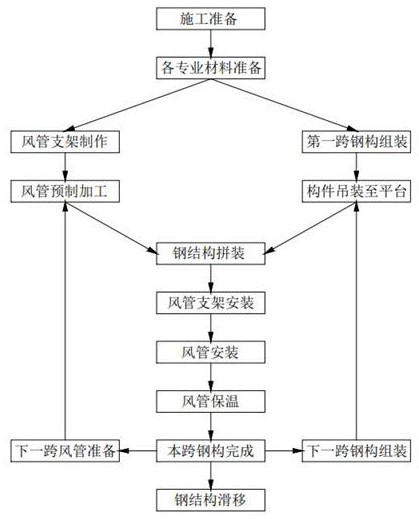
[0043] The embodiment of the present invention discloses a synchronous sliding construction method of a roof steel structure and an air duct, which includes the following construction steps:

[0044] S1. Model the entire system through BIM software, determine the structure and location of the air duct, including the size parameters and position information of the air duct, and the structure and position information of the steel structure support;

[0045] S2. Prefabricate construction materials and devices according to the data of the BIM model, including the prefabrication processing of the air duct support and the prefabrication processing of the steel structure support;

[0046] S3. Install the sliding track and the sliding assembly platform;

[0047] S4, assembling the steel structure support, including ground assembly and hoisting of the steel structure support;

[0048] S5. Install the air duct support, and perform hoisting of the air duct according to the position info...

Embodiment 2

[0058] Based on embodiment 1, the following technical solutions can be adopted:

[0059] The air ducts are hoisted in groups and installed in order to connect the air duct groups. The joints of the air duct groups are connected by flange bolts and the edges of the flanges are coated with sealant. The flanges are padded with flame retardant materials. .

[0060] The flame retardant material is a 4mm thick flame retardant closed cell sponge rubber strip.

[0061] The sliding speed of the overall sliding is 5-8m / h.


PUM


Abstract

The invention relates to the technical field of supporting building facility construction. The method comprises the following construction steps that modeling is conducted on a whole system through BIM software, and the structure and position of an air duct are at least determined and at least comprise the size parameter and position information of the air duct and the structure and position information of a steel structure support; construction materials and devices are prefabricated according to data of a BIM model, and at least prefabrication machining of an air duct support and prefabrication machining of the steel structure support are included; a sliding rail and a sliding assembly platform are installed; the steel structure support is assembled, and ground assembling and hoisting of the steel structure support are included; the air duct support is installed, and the air duct is hoisted according to the air duct position information of the BIM model; and overall sliding is conducted. The steel structure support and the air duct are installed in a span-separated manner, each span is installed on the sliding assembly platform, then the steel structure support and the air duct overall slide to the sliding rail, the hoisting difficulty of large-span roof operation is avoided, and the installation efficiency and installation precision are improved through an information management system of the BIM.

Description

technical field [0001] The invention relates to the technical field of construction of supporting building facilities, in particular to a synchronous sliding construction method of a roof steel structure and an air duct. Background technique [0002] At present, the rapid construction of national stadiums has become a new architectural topic, and the construction technology of electromechanical pipelines sliding with steel structures just solves the problem of rapid construction of stadiums with sliding steel structure roofs. The mechanical and electrical pipelines in the steel truss are designed to be high in height and heavy in weight, and the pipelines are interspersed in the web members of the steel structure, so the direction is complicated. Conventional construction cannot meet the schedule requirements of the construction period. Due to the influence of the lower chord of the steel structure, the later pipeline transportation and hoisting will be affected, and the con...

Claims


Application Information

Patent Timeline
Patent Type & Authority Applications(China)
IPC IPC(8): E04G21/14E04G21/16
CPCE04G21/14E04G21/161E04G21/162
Inventor 安超张晓天李少华杨波盛强李捷王洪申庆赟
Owner CHINA CONSTR EIGHTH ENG DIV
Learn More