Vibration and noise reduction air compressor room and construction method

An air compressor room, vibration reduction and noise reduction technology, applied in mechanical equipment, industrial buildings, machines/engines, etc., can solve the problems of affecting the use effect, adverse health, strong noise, etc., to improve the use effect, easy to promote The effect of using and reducing noise

Active Publication Date: 2021-10-29
广东省六建集团有限公司
7 Cites 0 Cited by

AI-Extracted Technical Summary

Problems solved by technology

However, the current air compressor room has large vibration and strong noise. Working in an environment wit...

Method used

Based on the vibration reduction and noise reduction air compressor room of the above-mentioned technical characteristics, by setting the sound-absorbing ceiling 2 on the top of the room body 1, and installing the sound insulation door 3 in the door frame 13, the noise transmission inside the room body 1 can be effectively prevented to the outside, thereby reducing the noise outside the air compressor room. At the same time, the air compressor 5 and the air storage tank 6 are installed by setting the damping spring shock absorber 7, and the spring hanger shock absorber 8 is connected to the pipeline 4, which can effectively reduce the noise of the vibration source, and further realize vibration reduction and noise reduction, thereby The vibration and noise reduction of the air compressor room is realized, and the use effect is improved. The invention has the advantages of simple structure, good use effect and easy popularization and use.
In addition, for convenience of construction and further guarantee damping effect, described damping platform 9 is fixedly provided with ground ridge 95, and described damping platform 9 is located in described ground ridge 95, and described ground ridge 95 and An asphalt sealing layer 96 is filled between the damping platforms 9, and a lateral anti-vibration plate is arranged between the asphalt sealing layer 96 and the damping platform, and the lateral anti-vibration plate can play a role of lateral damping. Vibration, to further ensure the effect of vibration reduction.
Please refer to accompanying drawing 3, in the present embodiment, described damping spring shock absorber 7 comprises fixed connection plate 71, and described fixed connection plate 71 is provided with housing 72, and described housing 72 is connected with described Rubber vibration-damping pads 73 are arranged between the plates 71, and the rubber vibration-damping pads 73 play a role of vibration-damping, and the housing 72 and the rubber vibration-damping pads 73 are connected by bolts. During installation, the fixed connection plate 71 is fixedly installed on the foundation 100, and then the air compressor 5 or the air storage tank 6 is installed on the housing 72. The installation is simple and convenient, and the vibration reduction effect is good.
Please refer to accompanying drawing 4, in the present embodiment, described spring hanger shock absorber 8 comprises frame body 81 and lower boom 82, and the upper end of described frame body 81 is provided with upper boom 83, and described frame body 81 is provided with a through hole, the inside of the frame 81 is provided with a telescopic spring 84 and a positioning plate 85, and the telescopic spring 84 is located between the through hole and the positioning plate 85, and the lower boom The upper end of 82 sequentially passes through the through hole, the telescopic spring 84 and the positioning plate 85 to connect to the first nut 86, and the telescopic spring 84 plays a role of damping. At the same time, in order to further improve the damping effect, the upper end of the frame body 81 is provided wit...

Abstract

The invention relates to the technical field of air compressor rooms, and discloses a vibration and noise reduction air compressor room and a construction method. The vibration and noise reduction air compressor room comprises a room body; a sound absorption ceiling is arranged at the top of the room body; an air inlet, an air outlet and a door frame are arranged on the side wall of the room body; a sound insulation door is arranged in the door frame in an openable and closable mode; an air compressor and an air storage tank which are connected through a pipeline are arranged in the room body; the air compressor and the air storage tank are installed on a foundation through damping spring shock absorbers; and the pipeline is connected to a roof through spring hanger shock absorbers. According to the vibration and noise reduction air compressor room and the construction method, a sound absorption ceiling is arranged at the top of the room body, and the sound insulation door is installed in the door frame, such that noise in the room body can be effectively prevented from being transmitted to the outside, and the outdoor noise of the air compressor room is reduced. The damping spring shock absorbers are arranged to install the air compressor and the air storage tank, and the spring hanger shock absorbers are arranged to be connected to the pipeline, such that noise of a vibration source can be effectively reduced, vibration and noise are further reduced, vibration and noise reduction of the air compressor room is achieved, and the using effect is improved.

Application Domain

CeilingsPositive displacement pump components +5

Technology Topic

EngineeringAir compressor +4

Image

  • Vibration and noise reduction air compressor room and construction method
  • Vibration and noise reduction air compressor room and construction method
  • Vibration and noise reduction air compressor room and construction method

Examples

  • Experimental program(1)

Example Embodiment

[0038] The specific implementation manners of the present invention will be further described in detail below in conjunction with the accompanying drawings and embodiments. The following examples are used to illustrate the present invention, but are not intended to limit the scope of the present invention.
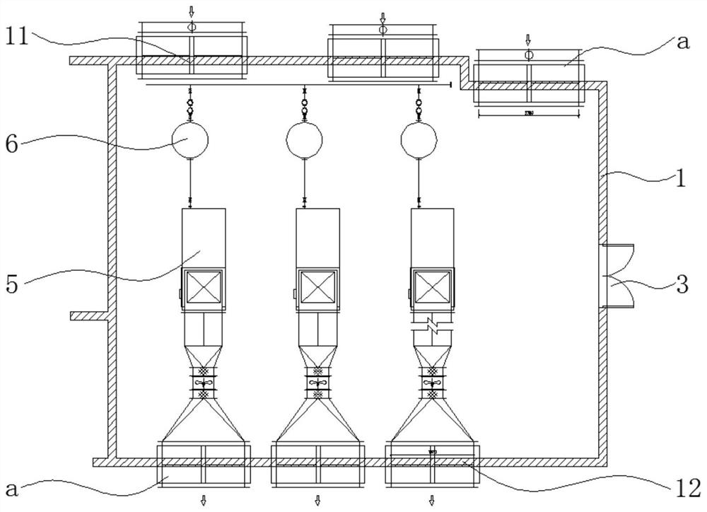
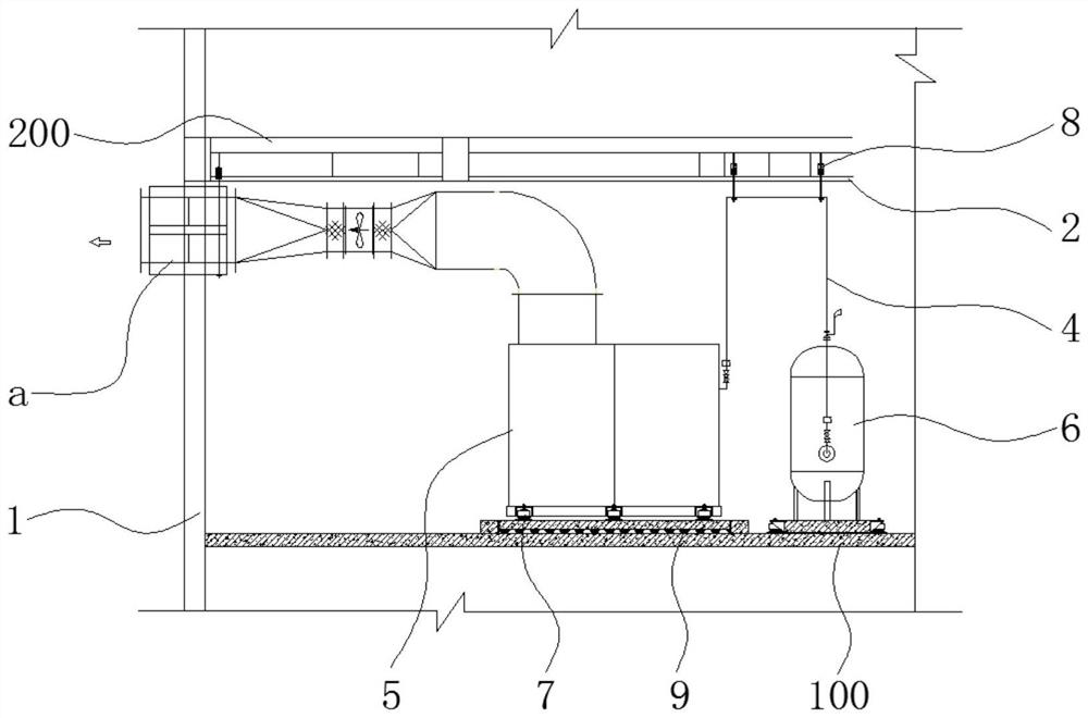
[0039] like Figure 1-2 As shown, a vibration-reducing and noise-reducing air compressor room in a preferred embodiment of the present invention includes a room body 1, a sound-absorbing ceiling 2 is provided on the top of the room body 1, and a sound-absorbing ceiling 2 is provided on the side wall of the room body 1. There is an air inlet 11, an air outlet 12 and a door frame 13. The door frame 13 is provided with a soundproof door 3 which can be opened and closed. The inside of the room body 1 is provided with an air compressor 5 and an air storage tank 6 connected by a pipe 4. , and the air compressor 5 and the air storage tank 6 are installed on the foundation 100 through the damping spring shock absorber 7, and the pipeline 4 is connected to the roof 200 through the spring hanger shock absorber 8. When connecting, the two spring hanger shock absorbers 8 are connected to a support, and the pipeline 4 is placed on the support.
[0040] Based on the above-mentioned technical features, the air compressor room with vibration and noise reduction can effectively prevent the noise inside the room 1 from being transmitted to the outside by installing a sound-absorbing ceiling 2 on the top of the room body 1 and installing a sound-insulating door 3 in the door frame 13. Thereby reducing the noise outside the air compressor room. At the same time, the air compressor 5 and the air storage tank 6 are installed by setting the damping spring shock absorber 7, and the spring hanger shock absorber 8 is connected to the pipeline 4, which can effectively reduce the noise of the vibration source, and further realize vibration reduction and noise reduction, thereby The vibration and noise reduction of the air compressor room is realized, and the use effect is improved. The invention has the advantages of simple structure, good use effect and easy popularization and use.
[0041] Please refer to the attached image 3 , in this embodiment, the damping spring shock absorber 7 includes a fixed connection plate 71, a housing 72 is arranged on the fixed connection plate 71, and a rubber damper is arranged between the housing 72 and the connection plate 71. The vibration pad 73, the rubber vibration damping pad 73 plays a role of vibration reduction, and the housing 72 and the rubber vibration damping pad 73 are connected by bolts. During installation, the fixed connection plate 71 is fixedly installed on the foundation 100, and then the air compressor 5 or the air storage tank 6 is installed on the housing 72. The installation is simple and convenient, and the vibration reduction effect is good.
[0042] Please refer to the attached Figure 4 , in this embodiment, the spring hanger shock absorber 8 includes a frame body 81 and a lower boom 82, the upper end of the frame body 81 is provided with an upper boom 83, and the bottom of the frame body 81 is provided with a through hole, The interior of the frame body 81 is provided with a telescopic spring 84 and a positioning plate 85, and the telescopic spring 84 is located between the through hole and the positioning plate 85, and the upper end of the lower boom 82 passes through the The through hole, the telescopic spring 84 and the positioning plate 85 are connected to the first nut 86, and the telescopic spring 84 plays a role of damping. At the same time, in order to further improve the damping effect, the upper end of the frame body 81 is provided with a hanging hole, and the upper hanging rod 83 passes through the hanging hole to connect the second nut 87, and the connection between the second nut 87 and the hanging hole A rubber pad 88 is arranged between them, and the rubber pad 88 has the effect of further damping vibration. During actual installation, the heights of the upper boom 83 and the lower boom 82 can be selected according to needs.
[0043] Please refer to the attached Figure 5-7, because the noise in the air compressor room is mainly generated by the air compressor 5, in order to further improve the vibration reduction effect, a vibration reduction platform 9 is provided on the foundation 100, and the air compressor 5 is damped by the damping spring. The vibrator 7 is installed on the damping platform 9; the damping platform 9 includes a rubber vibration and sound insulation pad 91, an asphalt waterproof coiled material layer 92, a reinforced concrete board 93 and a surface that are sequentially arranged upward along the foundation 100. layer 94, and the ratio of the thickness of the asphalt waterproof membrane layer 92 to the reinforced concrete slab 93 is 1:45-1:55, such as the thickness of the asphalt waterproof membrane layer 92 is 2 mm, the steel bar The thickness of the concrete plate 93 is 100 mm, which can not only play a waterproof role, but also ensure strength.
[0044] In addition, in order to facilitate construction and further ensure the vibration reduction effect, a ridge 95 is fixed on the vibration reduction platform 9, and the vibration reduction platform 9 is arranged in the ridge 95, and the ridge 95 and the vibration reduction platform 9 An asphalt sealing layer 96 is filled between the vibrating platforms 9, and a lateral anti-vibration plate is provided between the asphalt sealing layer 96 and the vibration-damping platform, and the lateral anti-vibration plate can play a role of lateral vibration reduction. Further ensure the vibration damping effect.
[0045] Preferably, the rubber vibration and sound insulation pad 91 includes a square pad body 911, the lower surface of the pad body 911 is arranged in a rectangular array with a number of rubber particles 912 evenly distributed, and between two adjacent rubber particles 912 The spacing is s, the side length of the pad body 911 is a, s=0.15-0.2a;
[0046] In order to further ensure the damping effect of the rubber particles 912, the rubber particles 912 are in the shape of a truncated cone, and the angle between its busbar and the center line is 50-70 degrees, such as 60 degrees, 65 degrees, etc., and its large bottom surface end Connected to the pad body 911, its small bottom surface end is provided with a vibration-damping groove 913, and the width of the vibration-damping groove 913 is 0.3-0.4 times the diameter of the small bottom surface of the rubber particle 912, and the small bottom surface end of the rubber particle 912 Against the foundation 100.
[0047] Please refer to the attached Figure 8 , in this embodiment, the inner side of the door frame 13 is provided with a sound insulation sealing strip 31; the sound insulation door 3 includes two opposite door panels 32, the door panels 32 are made of galvanized steel, and the two door panels 32 Fill with soundproof cotton 33 between them, the thickness of described soundproof cotton 33 should guarantee, fill 60 kilograms of soundproof cotton as between the galvanized sheet of thickness of 1.5, guarantee soundproof effect. The door panel 32 is provided with a handle, which is convenient for opening or closing the soundproof door 3 .
[0048] Please refer to the attached Figure 9 , in this embodiment, the air inlet 11 and the air outlet 12 are provided with a muffler a, and the muffler a includes a flat box a1, and the inside of the box a1 is provided with a muffler sheet a2 at intervals, A noise-absorbing channel a3 is formed between the adjacent noise-absorbing sheets a2, so as to ensure a good vibration-reducing and noise-reducing effect when the air enters and exits the air. At the same time, through a large number of experimental surfaces, the width of the noise reduction channel a3 is the same as the thickness of the noise reduction sheet a2, and when the air inlet end of the noise reduction sheet a2 is provided with a diversion cap a3, the noise reduction effect optimal.
[0049] In order to solve the above technical problems, the present invention also provides a construction method for a vibration and noise reduction air compressor room, comprising the following steps:
[0050] Construction room body 1, and air inlet 11, air outlet 12 and door frame 13 are set respectively on the side wall of described room body 1, and the inner side of described door frame 13 should be provided with soundproof sealing strip 31;
[0051] A foundation 100 is poured in the house body 1, and the foundation 100 can be the ground of the first floor, the ground of the basement, or the upper surface of the floors above the second floor;
[0052] A damping platform 9 is set on the foundation 100 . The damping platform 9 includes a rubber vibration and sound insulation pad 91, an asphalt waterproof coiled material layer 92, a reinforced concrete plate 93 and a surface layer 94 arranged upwards along the foundation 100, and the asphalt waterproof coiled material layer 92 and the The ratio of the thickness of the reinforced concrete board 93 is 1:45-1:55, as the thickness of the asphalt waterproof coiled material layer 92 is 2 millimeters, the thickness of the reinforced concrete board 93 is 100 millimeters, both can play The waterproof function can also guarantee the strength.
[0053] In addition, in order to facilitate construction and further ensure the vibration reduction effect, a ridge 95 is fixed on the vibration reduction platform 9, and the vibration reduction platform 9 is arranged in the ridge 95, and the ridge 95 and the vibration reduction platform 9 An asphalt sealing layer 96 is filled between the vibrating platforms 9, and a lateral anti-vibration plate is provided between the asphalt sealing layer 96 and the vibration-damping platform, and the lateral anti-vibration plate can play a role of lateral vibration reduction. Further ensure the vibration damping effect.
[0054] Preferably, the rubber vibration and sound insulation pad 91 includes a square pad body 911, the lower surface of the pad body 911 is arranged in a rectangular array with a number of rubber particles 912 evenly distributed, and between two adjacent rubber particles 912 The spacing is s, the side length of the pad body 911 is a, s=0.15-0.2a;
[0055] In order to further ensure the damping effect of the rubber particles 912, the rubber particles 912 are in the shape of a truncated cone, and the angle between its busbar and the center line is 50-70 degrees, such as 60 degrees, 65 degrees, etc., and its large bottom surface end Connected to the pad body 911, its small bottom surface end is provided with a vibration-damping groove 913, and the width of the vibration-damping groove 913 is 0.3-0.4 times the diameter of the small bottom surface of the rubber particle 912, and the small bottom surface end of the rubber particle 912 against the foundation 100;
[0056] Install damping spring shock absorber 7 respectively on described shock absorbing platform 9 and described foundation 100, the quantity of described damping spring shock absorber 7 is determined according to actual conditions, but preferably is installed on one described shock absorbing platform 9 6 pieces, 6 pieces of the damping spring shock absorber 7 are also installed under one of the air storage tanks 6;
[0057] Install the air compressor 5 and the air storage tank 6 respectively on the damping spring shock absorber 7, and the air compressor 5 is communicated with the air storage tank 6;
[0058] Install the spring hanger shock absorber 8 and the sound-absorbing ceiling 2 on the roof 200;
[0059] A pipeline 4 is connected to the spring hanger shock absorber 8, and the pipeline 4 communicates with the air compressor 5 and the air storage tank 6 respectively. When the pipeline 4 passes through the wall, it needs to be sealed with sound insulation, and the sound insulation is treated with ultra-fine glass wool above 48K and waterproof cement glue.
[0060] In addition, in addition to strict sound insulation and sealing measures for the pipe 4 through the wall, vibration isolation treatment must also be done, using rubber vibration isolation pads and fireproof mud glue for flexible sealing;
[0061] A muffler is respectively installed at the air inlet 11 and the air outlet 12 . The muffler a includes a flat box a1, the interior of the box a1 is provided with mufflers a2 at intervals, and a muffler channel a3 is formed between the adjacent mufflers a2, thereby ensuring the air inlet and outlet It has good vibration and noise reduction effect. At the same time, through a large number of experimental surfaces, the width of the noise reduction channel a3 is the same as the thickness of the noise reduction sheet a2, and when the air inlet end of the noise reduction sheet a2 is provided with a diversion cap a3, the noise reduction effect optimal. ;
[0062] The sound insulation door 3 is installed on the door frame 13 . The soundproof door 3 includes two oppositely arranged door panels 32, the door panels 32 are made of galvanized steel, and the sound insulation cotton 33 is filled between the two door panels 32, and the thickness of the sound insulation cotton 33 should be ensured, such as 1.5 60kg of sound-insulating cotton is filled between galvanized sheets of a certain thickness to ensure the sound-insulating effect. The door panel 32 is provided with a handle, which is convenient for opening or closing the soundproof door 3 .
[0063] It should be noted that the installation sequence of the above-mentioned structures may not be performed according to the above-mentioned steps.
[0064] The above is only a preferred embodiment of the present invention, it should be pointed out that for those of ordinary skill in the art, without departing from the technical principle of the present invention, some improvements and replacements can also be made, these improvements and replacements It should also be regarded as the protection scope of the present invention.

PUM

no PUM

Description & Claims & Application Information

We can also present the details of the Description, Claims and Application information to help users get a comprehensive understanding of the technical details of the patent, such as background art, summary of invention, brief description of drawings, description of embodiments, and other original content. On the other hand, users can also determine the specific scope of protection of the technology through the list of claims; as well as understand the changes in the life cycle of the technology with the presentation of the patent timeline. Login to view more.

Similar technology patents

Distributed video decoder and distributed video decoding method

ActiveUS20100177893A1reduce noiseimprove performance
Owner:RES & BUSINESS FOUNDATION SUNGKYUNKWAN UNIV

Classification and recommendation of technical efficacy words

  • Improve the use effect
  • reduce noise

A kind of bactericidal composition containing prothioconazole and thiocarbamate

InactiveCN102258039ADelay the occurrence and development of pathogen resistanceImprove the use effect
Owner:SHAANXI MEIBANG PHARMA GRP CO LTD

Audio synchronization method and system of bluetooth equipment

ActiveCN108111997AReduce audio latency differenceImprove the use effect
Owner:ZHUHAI JIELI TECH

Liver subsection method based on CT image and system thereof

InactiveCN101425186Areduce noiseavoid blur
Owner:HUAZHONG UNIV OF SCI & TECH

Noise reduction device

ActiveUS20100014683A1reduce noisehigh quality
Owner:PANASONIC CORP

Automatic image capture

ActiveUS20110170740A1reduce noiseenhance edge
Owner:NORTHWEST IP LLC +1
Why Eureka
Try Eureka