Anti-leakage and anti-winding debuggable tail shaft rear sealing device

An anti-leakage and anti-winding technology, which is applied to the sealing of the engine, engine components, mechanical equipment, etc., can solve the problems of lubricating oil backflow and damage to the machine, so as to avoid the entanglement and damage of debris, improve the anti-leakage shape, and increase the service life. Effect

Inactive Publication Date: 2021-10-29
重庆长源船舶设备有限公司
View PDF0 Cites 0 Cited by
  • Summary
  • Abstract
  • Description
  • Claims
  • Application Information

AI Technical Summary

Problems solved by technology

[0003] The purpose of the present invention is to at least solve one of the technical problems existing in the prior art, to provide an anti-leakage, anti-winding and adjustable tail shaft rear sealing device, which can solve the problem of lubricating oil backflow and damage to the machine

Method used


Image

  • Anti-leakage and anti-winding debuggable tail shaft rear sealing device
  • Anti-leakage and anti-winding debuggable tail shaft rear sealing device
  • Anti-leakage and anti-winding debuggable tail shaft rear sealing device

Examples


Embodiment 1

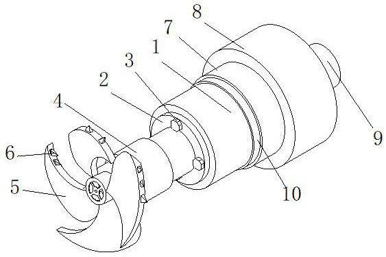
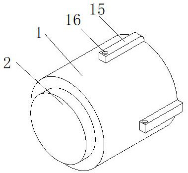
[0031] see Figure 1-6, the present invention provides a technical solution: an anti-leakage and anti-winding adjustable tail shaft rear sealing device includes a tail shaft body 1, the front surface of the tail shaft body 1 is provided with a wear-resistant sleeve 2, and the front surface of the wear-resistant sleeve 2 is Bolt 3 is threadedly connected, and wear-resistant sleeve 2 is connected with tail shaft body 1 through bolt 3. The front surface of wear-resistant sleeve 2 is fixedly connected with connecting shaft 4, and the front end of connecting shaft 4 is connected with propeller 5 in rotation. The outer wall is fixedly connected with a sharp cutting board 6. When using the device, when the propeller 5 rotates, the cutting board 6 is driven to rotate. Through the rotation of the cutting board 6, the sundries attached to the propeller 5 can be cut and pulverized, thereby Prevent the propeller 5 from being entangled with debris, thereby avoiding the damage of the propel...

Embodiment 2

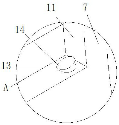
[0034] Example two; see Figure 1-6 , on the basis of Embodiment 1, the rear surface of the sealing block 8 is provided with a threaded hole 22, and the inside of the sealing block 8 is provided with an anti-leakage device. Inside, the front and rear ends of the threaded rod 18 run through the sealing block 8, the front end of the threaded rod 18 is fixedly connected with a piston 19, and the piston 19 is slidably connected to the inside of the sealing block 8, the piston 19 has a sealing effect, and the rear end of the threaded rod 18 is in contact with the rotating The plug 9 is fixedly connected, and the inner front side of the sealing block 8 is provided with a communication groove 20 communicating with the inside of the O-ring 7. The inside of the O-ring 7 is provided with a waterproof air bag 21 communicating with the communication groove 20. The waterproof air bag 21 and the oil storage ring 12 contacts.

[0035] Further, when using the device, the rotation of the plug...


PUM


Abstract

The invention discloses an anti-leakage and anti-winding debuggable tail shaft rear sealing device, and relates to the technical field of tail shaft sealing. The anti-leakage and anti-winding debuggable tail shaft rear sealing device comprises a tail shaft body, a wear-resisting sleeve is arranged on the front surface of the tail shaft body, a bolt is in threaded connection with the front surface of the wear-resisting sleeve, a connecting shaft is fixedly connected to the front surface of the wear-resisting sleeve, a propeller is rotationally connected to the front end of the connecting shaft, and an O-shaped ring is arranged on the rear side of the tail shaft body. The rear end of the O-shaped ring is fixedly connected with a hollow sealing block, a threaded hole is formed in the rear surface of the sealing block, and an anti-leakage device is arranged in the sealing block. Through the arrangement of the anti-leakage device, lubricating oil can be effectively prevented from flowing back into the device on the rear side, the leakage-proof performance of the whole device can be effectively improved through the arrangement of the leakage-proof device, meanwhile, a protection effect is achieved on a machine connected with the tail shaft body, and the lubricating oil in the tail shaft is prevented from flowing back into the machine to avoid damaging the machine.

Description

technical field [0001] The invention relates to the technical field of tail shaft sealing, in particular to a leak-proof, anti-winding and adjustable tail shaft rear sealing device. Background technique [0002] The stern shaft, also known as the stern shaft, is the last shaft in the shaft system. The flange at the head end is connected to the flange of the intermediate shaft with tight fit bolts; the tail end is conical and used to install the propeller. Forged from high quality carbon steel. The working conditions of the stern shaft are relatively harsh. It is not only easily corroded by seawater, but also will be twisted and subjected to bending alternating stress, resulting in various failures. Most of the existing stern shafts need to add lubricating oil inside during use. Guaranteed to reduce the friction force when the tail shaft rotates, reduce the wear of the tail shaft, and improve the service life of the tail shaft. However, once the lubricating oil in the tail ...

Claims


Application Information

Patent Timeline
Patent Type & Authority Applications(China)
IPC IPC(8): F16J15/16
CPCF16J15/16
Inventor 陈学炳黎超陈俊鹏
Owner 重庆长源船舶设备有限公司
Why Eureka
Try Eureka