Electromagnetic eddy current heating device for waste oil residues

An electromagnetic eddy current and heating device technology, applied in the direction of pipeline heating/cooling, pipe/pipe joint/pipe fitting, pipeline system, etc., can solve the problems of high labor intensity, inability to transfer, unsafe, etc., achieve scientific and reasonable structure and reduce labor Strength, the effect of ensuring smooth flow

Pending Publication Date: 2021-10-29
CHONGQING FANGSHENG CLEANING EQUIP CO LTD
View PDF0 Cites 0 Cited by
  • Summary
  • Abstract
  • Description
  • Claims
  • Application Information

AI Technical Summary

Problems solved by technology

When waste oil is regenerated, a large amount of waste oil residue will be produced, and the total amount of waste oil residue is as high as 25% of the total waste oil. In waste oil regeneration, waste oil residue is mainly deposited in the reaction kettle, thin film evaporator, and pretreatment tank Waiting for the bottom of the tank, at a certain time, the waste oil residue needs to be transferred to the waste oil residue tank. Because the fluidity of the waste oil residue is very poor, especially when the temperature of the waste oil residue is at normal temperature, it does not flow at all and cannot be transferred.
In the past, the waste oil residue at the bottom of the reactor, thin-film evaporator, and pretreatment tank was directly discharged to the ground at high temperature, and then manually re-transported. This method is not safe, labor-intensive, and is prone to major accidents. , the transfer technology of waste oil residue needs to be improved, and an electromagnetic eddy current heating device for waste oil residue needs to be explored

Method used


Image

  • Electromagnetic eddy current heating device for waste oil residues

Examples


Embodiment 1

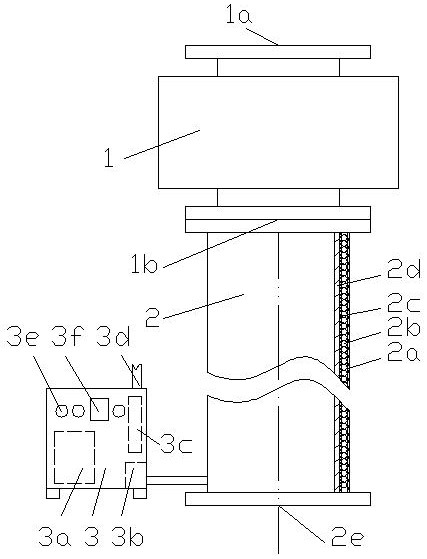
[0014] refer to figure 1 , an electromagnetic eddy current heating device for waste oil residue, the electromagnetic eddy current heating device for waste oil residue is formed by connecting a delivery pump 1, an energy regenerator 2, and an electromagnetic heating controller 3; the delivery pump 1 is provided with a delivery pump feeding port 1a, delivery pump discharge port 1b; the energy regenerator 2 is provided with an insulation layer 2c, an electromagnetic heating coil 2b, and a protective layer 2a outside the tank body wall 2d, and the tank body wall 2d is made of stainless steel, and the tank body wall One end of 2d is an oil residue inlet, and the other end is a waste oil residue outlet 2e; the electromagnetic heating controller 3 is provided with a box body, an electromagnetic generator 3a, an output end 3b, a circuit board 3c, a power input end 3d, The control switch 3e, the display panel 3f; the discharge port 1b of the delivery pump is connected to the oil residu...

Embodiment 2

[0016] refer to figure 1 , an electromagnetic eddy current heating device for waste oil residue, the electromagnetic eddy current heating device for waste oil residue is formed by connecting a delivery pump 1, an energy regenerator 2, and an electromagnetic heating controller 3; the delivery pump 1 is provided with a delivery pump feeding port 1a, delivery pump discharge port 1b; the energy regenerator 2 is provided with an insulation layer 2c, an electromagnetic heating coil 2b, and a protective layer 2a outside the tank body wall 2d, and the tank body wall 2d is made of stainless steel, and the tank body wall One end of 2d is an oil residue inlet, and the other end is a waste oil residue outlet 2e; the electromagnetic heating controller 3 is provided with a box body, an electromagnetic generator 3a, an output end 3b, a circuit board 3c, a power input end 3d, The control switch 3e, the display panel 3f; the discharge port 1b of the delivery pump is connected to the oil residu...

Embodiment 3

[0018] refer to figure 1 , an electromagnetic eddy current heating device for waste oil residue, the electromagnetic eddy current heating device for waste oil residue is formed by connecting a delivery pump 1, an energy regenerator 2, and an electromagnetic heating controller 3; the delivery pump 1 is provided with a delivery pump feeding port 1a, delivery pump discharge port 1b; the energy regenerator 2 is provided with an insulation layer 2c, an electromagnetic heating coil 2b, and a protective layer 2a outside the tank body wall 2d, and the tank body wall 2d is made of stainless steel, and the tank body wall One end of 2d is an oil residue inlet, and the other end is a waste oil residue outlet 2e; the electromagnetic heating controller 3 is provided with a box body, an electromagnetic generator 3a, an output end 3b, a circuit board 3c, a power input end 3d, The control switch 3e, the display panel 3f; the discharge port 1b of the delivery pump is connected to the oil residu...


PUM

PropertyMeasurementUnit
Thicknessaaaaaaaaaa
Diameteraaaaaaaaaa
Lengthaaaaaaaaaa

Abstract

The invention discloses an electromagnetic eddy current heating device for waste oil residues and relates to a heating device for waste oil regeneration. The electromagnetic eddy current heating device for the waste oil residues is formed by connecting a conveying pump, an energy regenerator and an electromagnetic heating controller, wherein a conveying pump feed port and a conveying pump discharge port are formed in the conveying pump; the structure of the energy regenerator is that a heat preservation layer, an electromagnetic heating coil and a protection layer are arranged outside a tank wall, the tank wall is made of stainless steel, an oil residue inlet is formed in one end of the tank wall, and a waste oil residue outlet is formed in the other end of the tank wall; and the output end of the electromagnetic heating controller is connected with the electromagnetic heating coil. The device is scientific and reasonable in structure, ingeniously solves the problem of long-distance automatic conveying of discharged waste oil residues at the bottoms of a reaction kettle, a film evaporator and a pretreatment tank, guarantees smooth flowing of the waste oil residues, solves the potential safety hazards during discharging and transferring of the waste oil residues, greatly reduces the labor intensity of operators, is beneficial to safe production of waste oil regeneration, achieves automatic production, and has popularization value.

Description

technical field [0001] The invention relates to a heating device for waste oil regeneration, and more particularly relates to an electromagnetic eddy current heating device for waste oil residue. Background technique [0002] Waste oil means that after the oil has been used for a period of time, due to the immersion of pollution impurities and the oxidative deterioration of some components, the oil that cannot be used and replaced is collectively referred to as waste oil. When the waste oil is regenerated, a large amount of waste oil residue is produced, and the total amount of waste oil residue is as high as 25% of the total waste oil. In the waste oil regeneration, the waste oil residue is mainly deposited in the reaction kettle, thin film evaporator, and pretreatment tank Wait for the bottom of the tank body, and at a certain time, the waste oil residue needs to be transferred to the waste oil residue tank. Because the waste oil residue has poor fluidity, especially when ...

Claims


Application Information

Patent Timeline
IPC IPC(8): F17D1/14F17D1/18F17D3/01F16L53/34
CPCF17D1/14F17D1/18F17D3/01F16L53/34
Inventor 豆远奎
Owner CHONGQING FANGSHENG CLEANING EQUIP CO LTD
Why Eureka
Try Eureka