LiDAR optical system and LiDAR system

A laser radar and optical system technology, which is applied in the field of optical systems and laser radar systems, can solve the problems of weakening the detection angle of the radar system, the detection distance is not long enough, and the energy of the beam echo is limited, so as to improve the utilization rate of light energy and improve the The effect of clear aperture and increased beam width

Active Publication Date: 2022-05-10
ZVISION TECH CO LTD
View PDF14 Cites 0 Cited by
  • Summary
  • Abstract
  • Description
  • Claims
  • Application Information

AI Technical Summary

Problems solved by technology

[0003] However, in order to meet the vibration requirements of vehicle regulations, the MEMS aperture is generally relatively small, but this limits the light aperture of the entire radar system, which will result in limited beam echo energy and reduce the utilization of light energy. Although the MEMS coaxial solution can reduce Noise (environmental light), but the aperture of the light is limited by the aperture of the MEMS, so the detection distance is not far enough; if the aperture of the light is increased, it can be known from the theory of optical invariants that increasing the aperture of the light will inevitably lead to a decrease in the overall scanning field of view of the light output , weakening the detection angle of the entire radar system

Method used


Image

  • LiDAR optical system and LiDAR system
  • LiDAR optical system and LiDAR system
  • LiDAR optical system and LiDAR system

Examples


Embodiment Construction

[0041] In the following description, specific details such as specific system structures and technologies are presented for the purpose of illustration rather than limitation, so as to thoroughly understand the embodiments of the present invention. It will be apparent, however, to one skilled in the art that the invention may be practiced in other embodiments without these specific details. In other instances, detailed descriptions of well-known systems, devices, circuits, and methods are omitted so as not to obscure the description of the present invention with unnecessary detail.

[0042] In order to illustrate the technical solutions of the present invention, specific examples are used below to illustrate.

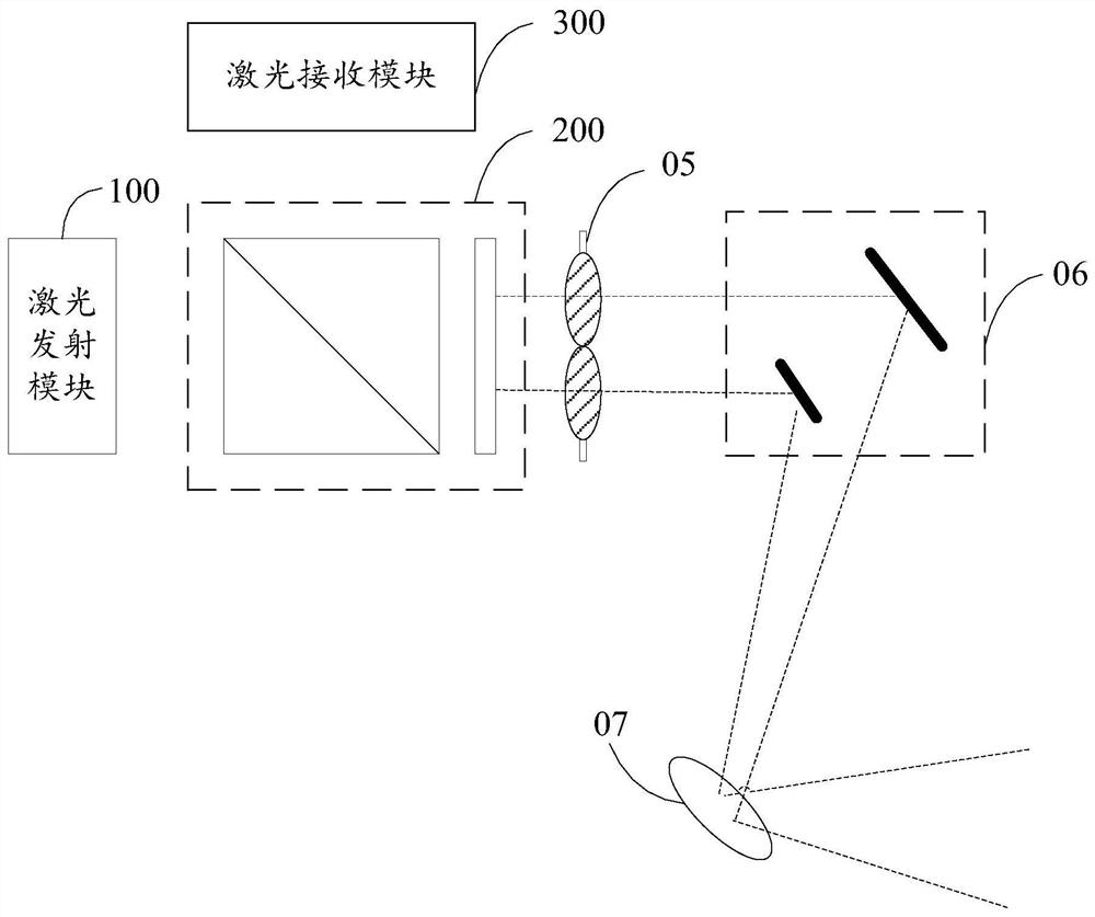
[0043] see figure 1 , this embodiment provides an optical system of a laser radar. For ease of description, only the parts related to this embodiment are shown.

[0044] The optical system of the laser radar in this embodiment mainly includes: a laser emitting module...


PUM


Abstract

The present invention relates to the technical field of laser radar, and provides a laser radar optical system and a laser radar system, including: a laser emitting module, which emits an initial beam; a beam splitting conversion module, which splits and processes the initial beam; a first lens group, including At least two focusing lenses with different focal lengths focus the beams after beam splitting; the mirror group includes at least two mirrors and reflects at least two focused beams to the MEMS scanning module; the MEMS scanning module converts the received The light beam is reflected to the target, and the returned light reflected by the received target is reflected to the mirror group; the mirror group reflects the returned light, and the returned light passes through the first lens group to the beam splitting conversion module; the beam splitting conversion module converts the received return light The light is converted into linearly polarized light and emitted; the laser receiving module outputs light detection values ​​according to the received linearly polarized light. The present invention increases the light aperture of the system without reducing the viewing angle of the light output scanning, has a high signal-to-noise ratio, and improves the utilization rate of light energy.

Description

technical field [0001] The invention relates to the technical field of laser radar, in particular to an optical system of laser radar and a laser radar system. Background technique [0002] LiDAR measures the position, speed, etc. of a target object by emitting a laser beam to the target object and receiving the beam reflected from the target object. With the rapid development of autonomous driving technology, MEMS (Micro-Electro-Mechanical System, micro-electro-mechanical optical scanning device) coaxial lidar is widely used due to the common optical path of transmitting and receiving and high signal-to-noise ratio. [0003] However, in order to meet the vibration requirements of vehicle regulations, the MEMS aperture is generally relatively small, but this limits the light aperture of the entire radar system, which will result in limited beam echo energy and reduce the utilization of light energy. Although the MEMS coaxial solution can reduce Noise (environmental light), ...

Claims


Application Information

Patent Timeline
Patent Type & Authority Patents(China)
IPC IPC(8): G01S17/02G01S7/481
CPCG01S17/02G01S7/4817G01S7/4812G01S17/42G01S7/00G01S7/4811G01S7/499G02B26/0816G02B26/105G02B27/09
Inventor 刘佳尧孟宪东石拓
Owner ZVISION TECH CO LTD
Why Eureka
Try Eureka