Sunglasses with miniature camera shooting function
A miniature camera and functional technology, applied in the field of sunglasses, can solve the problem of inconvenience for users to carry, and achieve the effects of improving overall performance, being easy to carry, and reducing space.
- Summary
- Abstract
- Description
- Claims
- Application Information
AI Technical Summary
Problems solved by technology
Method used
Image
Examples
Embodiment 1
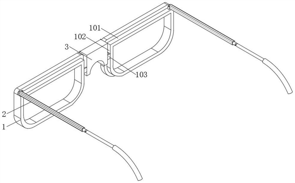
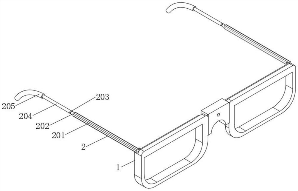
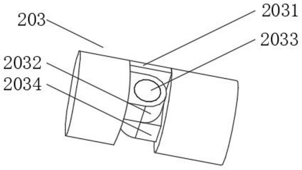
[0028] Embodiment one, by Figure 1-7 Given, the present invention includes a symmetrically arranged picture frame 1, the outer side of the picture frame 1 is equipped with a temple assembly 2, and the picture frame 1 is connected by a connecting block 3 in rotation, wherein the top of the picture frame 1 is provided with an upper groove 101, and the picture frame 1 There is a side groove 102 on the inner side of the side groove 102, and a U-shaped block 103 is installed in the middle of the side groove 102. The temple assembly 2 includes a cylinder 201 that is rotatably connected with the mirror frame 1, and an inner rod 202 is installed inside the cylinder 201. One end of the inner rod body 202 is equipped with a folding part 203, one end of the folding part 203 is equipped with a curved rod 204, and one end of the curved rod 204 is equipped with a rubber sleeve 205, the folding part 203 includes a stopper 2031 mounted on the curved rod 204 and Left connecting block 2032, an...
Embodiment 2
[0030] Embodiment 2, on the basis of Embodiment 1, a first groove 2011, a first screw hole 2012, a second groove 2013 and a second screw hole 2014 are provided inside the barrel 201, the first groove 2011 and the second screw hole 2014 are respectively provided. The inside of the first screw hole 2012 communicates, the first screw hole 2012 communicates with the inside of the second groove 2013, the second groove 2013 communicates with the inside of the second screw hole 2014, and the inside of the first screw hole 2012 is equipped with an adjustment member 4. One end of the adjustment part 4 is connected to the inner rod body 202, and the auxiliary part 5 is installed inside the second screw hole 2014, and the auxiliary part 5 is arranged correspondingly to the mirror frame 1, and the adjustment part 4 includes a connecting rod 401 connected to the inner rod body 202, One end of the connecting rod 401 is equipped with a first screw rod 402, the first screw rod 402 is threadedl...
Embodiment 3
[0032] Embodiment three, on the basis of embodiment two, the auxiliary part 5 includes a second screw 501 threadedly connected with the second screw hole 2014, and one end of the second screw 501 is equipped with a strip plate 502, and the strip plate 502 is connected to the strip Shaped groove 404 corresponding setting;
[0033] When it is necessary to adjust the maximum angle between the temple assembly 2 and the frame 1, it is only necessary to drive the inner rod body 202 to rotate through the curved rod 204, and the inner rod body 202 drives the first screw rod 402 to rotate by driving the connecting rod 401, and the first screw rod 402 passes through The threaded way moves into the second groove 2013, at this moment the first screw rod 402 is disconnected from the first screw hole 2012, and then moves and rotates the curved rod 204, so that the bar-shaped groove 404 in the first slide rod 403 is sleeved on the outside of the strip plate 502, thereby driving the strip pla...
PUM
 Abstract
Description
Claims
Application Information
 - R&D
- Intellectual Property
- Life Sciences
- Materials
- Tech Scout
- Unparalleled Data Quality
- Higher Quality Content
- 60% Fewer Hallucinations
Browse by: Latest US Patents, China's latest patents, Technical Efficacy Thesaurus, Application Domain, Technology Topic, Popular Technical Reports.
© 2025 PatSnap. All rights reserved.Legal|Privacy policy|Modern Slavery Act Transparency Statement|Sitemap|About US| Contact US: help@patsnap.com


