
Chip resistor and mounting structure thereof

A resistor and chip technology, applied in the direction of resistors, resistor assemblies, resistor components, etc., can solve the problems of reducing work efficiency, wasting time, small size of chip resistors, etc., and achieve the effect of increasing the scope of application

Inactive Publication Date: 2021-10-29
南京翰洋电子有限公司
View PDF0 Cites 2 Cited by
  • Summary
  • Abstract
  • Description
  • Claims
  • Application Information

AI Technical Summary

Problems solved by technology

[0003] Chip resistor is a kind of resistor. It is a current limiting element. It is a resistor made by mixing metal powder and glass glaze powder and printing on the substrate by screen printing. It is resistant to humidity and high temperature. The coefficient is small, but the use of chip resistors can greatly save the cost of circuit space and make the circuit design more refined. The existing chip resistors are small in size, so chip resistors are used in some test experiments, but the chip The resistance value of the chip resistor is a fixed value, and the resistance value cannot be changed. When the resistance value needs to be changed, it is often necessary to replace the chip resistor and then install it, which wastes a lot of time and reduces work efficiency.

Method used


Image

  • Chip resistor and mounting structure thereof
  • Chip resistor and mounting structure thereof
  • Chip resistor and mounting structure thereof

Examples


Embodiment Construction

[0026] The technical solution of this patent will be further described in detail below in conjunction with specific embodiments.

[0027] Embodiments of the present patent are described in detail below, examples of which are shown in the drawings, wherein the same or similar reference numerals designate the same or similar elements or elements having the same or similar functions throughout. The embodiments described below by referring to the figures are exemplary and are only used for explaining the patent, and should not be construed as limiting the patent.

[0028] In the description of this patent, it is to be understood that the terms "center", "upper", "lower", "front", "rear", "left", "right", "vertical", "horizontal", The orientation or positional relationship indicated by "top", "bottom", "inner", "outer", etc. is based on the orientation or positional relationship shown in the drawings, and is only for the convenience of describing this patent and simplifying the des...


PUM

PropertyMeasurementUnit
Boiling pointaaaaaaaaaa

Abstract

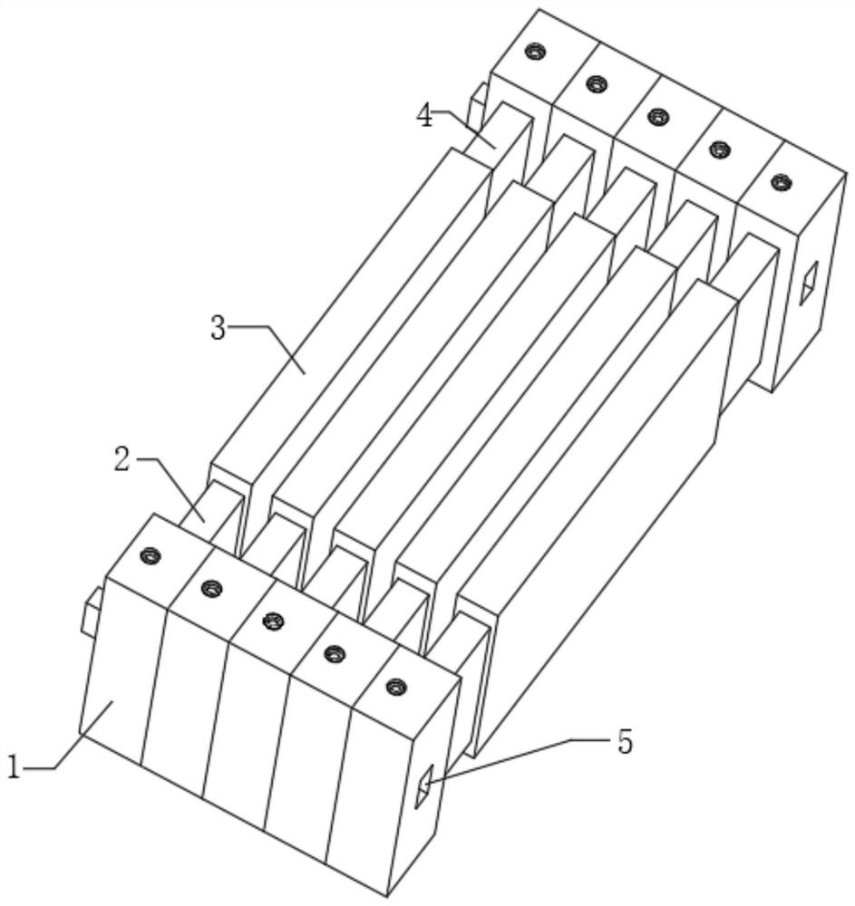
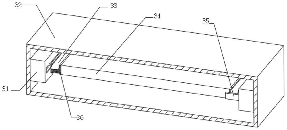
The invention discloses a chip resistor and a mounting structure thereof. The chip resistor comprises a resistor main body, wherein a first electrode and a second electrode are arranged on the outer walls of the two ends of the resistor body respectively, connecting boxes are arranged on the outer walls of one ends of the first electrode and the second electrode, mounting grooves are formed in the connecting boxes, an insertion box is fixedly connected to one side of each connecting box, a rotating shaft is rotatably connected to the top of the mounting groove, a knob is arranged at the top of the rotating shaft, a second bevel gear is fixedly connected to the outer wall of the bottom of the rotating shaft, a first bevel gear is meshed with one side of the second bevel gear, a first threaded rod is fixedly connected to the outer wall of one side of the first bevel gear, and the first threaded rod is rotatably connected to the joint of the connecting box and the insertion box. By arranging the insertion box, an arc-shaped reed, a clamping column, a half gear, the threaded rod I, the clamping groove, the clamping groove and the arc-shaped reed clamping groove, a plurality of resistor main bodies can be connected in series, and the resistance of the resistor can be changed, so that the application range of the resistor is greatly widened.

Description

technical field [0001] The invention relates to the technical field of chip resistors, in particular to a chip resistor and its installation structure. Background technique [0002] Chip resistors are also known as surface mount resistors. Like other chip components (SMC and SMD), they are a new generation of leadless or short lead microelectronic components suitable for surface mount technology (SMT). [0003] Chip resistor is a kind of resistor. It is a current limiting element. It is a resistor made by mixing metal powder and glass glaze powder and printing on the substrate by screen printing. It is resistant to humidity and high temperature. The coefficient is small, but the use of chip resistors can greatly save the cost of circuit space and make the circuit design more refined. The existing chip resistors are small in size, so chip resistors are used in some test experiments, but the chip The resistance value of the chip resistor is a fixed value, and the resistance v...

Claims


Application Information

Patent Timeline
IPC IPC(8): H01C7/00H01C13/02H01C1/14H01C1/144H01C1/014H01C1/08H01C1/084
CPCH01C7/001H01C13/02H01C1/14H01C1/014H01C1/08H01C1/084H01C1/144
Inventor 高文彪
Owner 南京翰洋电子有限公司
Learn More