Single crystal manufacturing device

A single crystal manufacturing device and single crystal technology, applied in the direction of single crystal growth, single crystal growth, crystal growth, etc., can solve problems such as failure to become a product, single crystal 104 slip dislocation, single crystal 104 separation, etc., to achieve growth The effect of increased speed

Pending Publication Date: 2021-10-29
SHIN-ETSU HANDOTAI CO LTD
View PDF7 Cites 0 Cited by
  • Summary
  • Abstract
  • Description
  • Claims
  • Application Information

AI Technical Summary

Problems solved by technology

Or, slip dislocations occur in the single crystal 104, or the single crystal 104 is separated from the melt and cannot be produced as a product, and there is a limit to the increase in the crystal growth rate.

Method used


Image

  • Single crystal manufacturing device
  • Single crystal manufacturing device
  • Single crystal manufacturing device

Examples


Embodiment 1

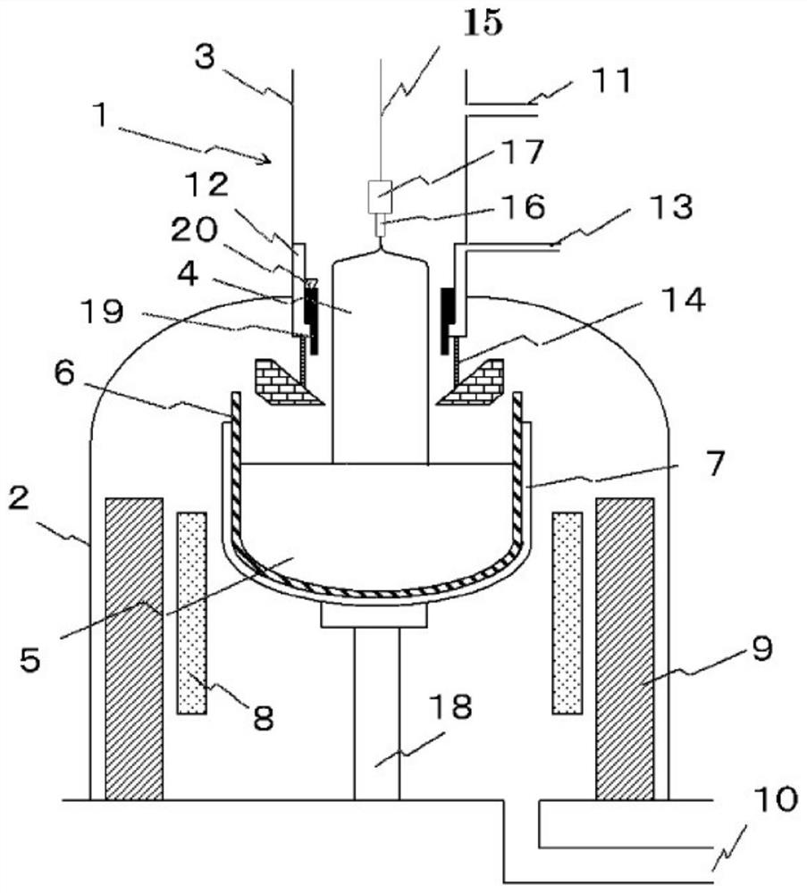
[0087] In Example 1, the following conditions are used. figure 1 The single crystal manufacturing apparatus 1 performs a growth of single crystal 4 and verifies the crystalline drawing speed of single crystal 4 capable of obtaining the desired quality.

[0088] The growth of single crystal 4 is single crystal silicon, and a silicon crystal having a diameter of 12 inches (300 mm) is produced by applying a magnetic field chroskichiometry (MCZ method). Quartz crucible 6 has a diameter of 32 inches (800 mm). The inner diameter of the cooling cylinder 12 is 430 mm, and the design value of the outer diameter of the cooling the auxiliary tube 19 is 429.5 mm, and its length is 350 mm. The tolerances of the outer diameter of the cooling cylinder 12 and the outer diameter of the cooling the auxiliary tube 19 are ± 0.4 mm, ± 0.1 mm, respectively.

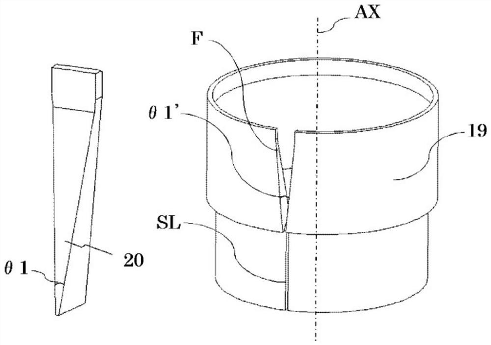
[0089] like figure 2 As shown, the components having a cracked SL through which are penetrated along the axial direction, and the upper portion o...

Embodiment 2

[0106] In Example 2, the following conditions are used. Figure 4 The single crystal manufacturing apparatus 1 'performs the growth of single crystal 4 and verifies the crystalline drawing speed of single crystal 4 capable of obtaining the desired quality.

[0107] The growth of single crystal 4 is single crystal silicon, except for use Figure 5 The cooling auxiliary cylinder 19 and the diameter enlargement member 20 were produced in the same conditions as in Example 1, and the same evaluation as in Example 1 was carried out. That is, the design value of the inner diameter of the cooling cylinder 12 is 430 mm, and the design value of the outer diameter of the cooling the auxiliary tube 19 is 429.5 mm, and the length is 350 mm. Further, the tolerance of the outer diameter of the cooling cylinder 12 and the outer diameter of the cooling the auxiliary tube 19 is ± 0.4 mm, ± 0.1 mm, respectively.

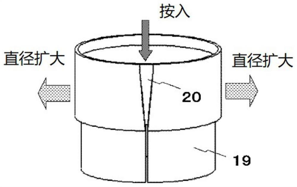
[0108] like Image 6 As shown, four cracks S1 through which are penetrated along the axia...


PUM

PropertyMeasurementUnit
diameteraaaaaaaaaa

Abstract

The present invention is a single crystal manufacturing device that uses the Czochralski method and comprises: a main chamber 2 that houses crucibles 6, 7 accommodating a source material melt 5, and a heater 8 for heating the source material melt 5; a drawing chamber 3 that is provided continuous with an upper section of the main chamber 2, and accommodates a single crystal 4 drawn up from the source material melt 5; a cooling cylinder 12 that extends from a ceiling section of the main chamber 2 toward the surface of the source material melt 5 so as to surround the single crystal 4; and a cooling assistance cylinder 19 that is fitted to the inside of the cooling cylinder 12, wherein the single crystal manufacturing device further comprises a diameter expansion member 20 that is fitted to the cooling assistance cylinder 19, and the cooling assistance cylinder 19 has an incision penetrating in an axial direction and adheres to the cooling cylinder 12 due to the diameter expansion member 20 being pressed into the incision, thereby expanding the diameter. Consequently, a single crystal in the process of being grown can be efficiently cooled, and an increase in the growth rate of said single crystal can be achieved.

Description

Technical field [0001] The present invention relates to a single crystal manufacturing apparatus using a checkerki method (CZOCHRALSKI Method, hereinafter referred to as CZ method). Background technique [0002] The following is an example of the growth of single crystal silicon by a single crystal manufacturing apparatus using the checlauski method. [0003] Figure 8 An example of a conventional single crystal manufacturing apparatus. [0004] The single crystal manufacturing apparatus 101 used when using a CZ method is made in general, and the connection is provided with a crucible 106, 107, and a lifting chamber 103 that houses the raw material melt 105 and can lift the activity, wherein the crucible is surrounded. The heater 108 disposed in 106, 107 is disposed in the main chamber 102 of the growth single crystal 104, which is used to accommodate single crystal 104 grown in the upper portion of the main chamber 102 and remove it. When such a single crystal manufacturing appa...

Claims


Application Information

Patent Timeline
Patent Type & Authority Applications(China)
IPC IPC(8): C30B29/06C30B15/14C30B30/04
CPCC30B29/06C30B15/14C30B15/20C30B30/04C30B15/007C30B15/10
Inventor 小林拓生柳濑和也冈井笃志园川将岩崎淳
Owner SHIN-ETSU HANDOTAI CO LTD
Why Eureka
Try Eureka