Holographic thoracoscope system

A thoracoscopy and thoracic cavity technology, applied in the field of holographic thoracoscopy system, can solve the problems of increasing the risk and difficulty of surgery, increasing the difficulty of surgery, and the interference of surgical instruments, so as to achieve the effect of facilitating early recovery, reducing incision damage, and saving manpower

Pending Publication Date: 2021-11-02
北京航天总医院
View PDF0 Cites 0 Cited by
  • Summary
  • Abstract
  • Description
  • Claims
  • Application Information

AI Technical Summary

Problems solved by technology

[0003] However, single-port thoracoscopic surgery is the same as the endoscopic system used in traditional multi-hole thoracoscopic surgery. Both enter the rod-shaped endoscopic system through the incision. Single-port thoracoscopic surgery needs to enter the endoscopic system through the same small incision, multiple operations Instruments, it is easy to cause the endoscopic system and surgical instruments to compete for the same operation incision, and interfere with each other with surgical instruments, which increases the risk and difficulty of the operation, and requires higher technical requirements for doctors. During the operation, a special endoscopic hand is required to operate the cavity The rod-shaped endoscopic system may increase the damage to the patient during the operation and cause chronic pain. In addition, the images obtained by the endoscopic system are transmitted to the monitor outside the operating table for display. The operator needs to look at the monitor during the operation. Think of the image on the image as the image of the operation area inside the thoracic cavity, which requires the operator to change the angle during the operation, which also increases the difficulty of the operation

Method used


Image

  • Holographic thoracoscope system
  • Holographic thoracoscope system
  • Holographic thoracoscope system

Examples


Embodiment Construction

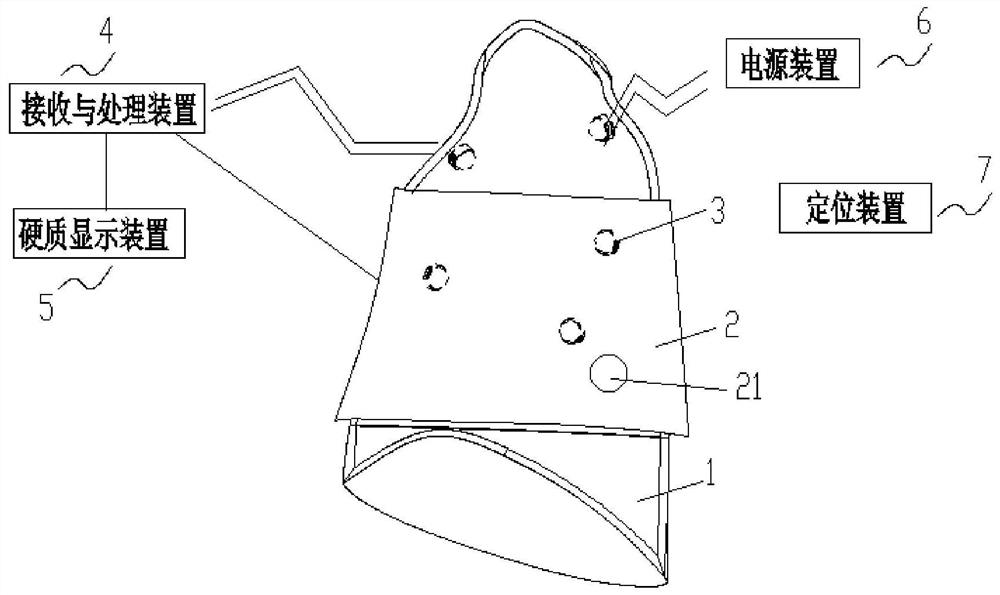
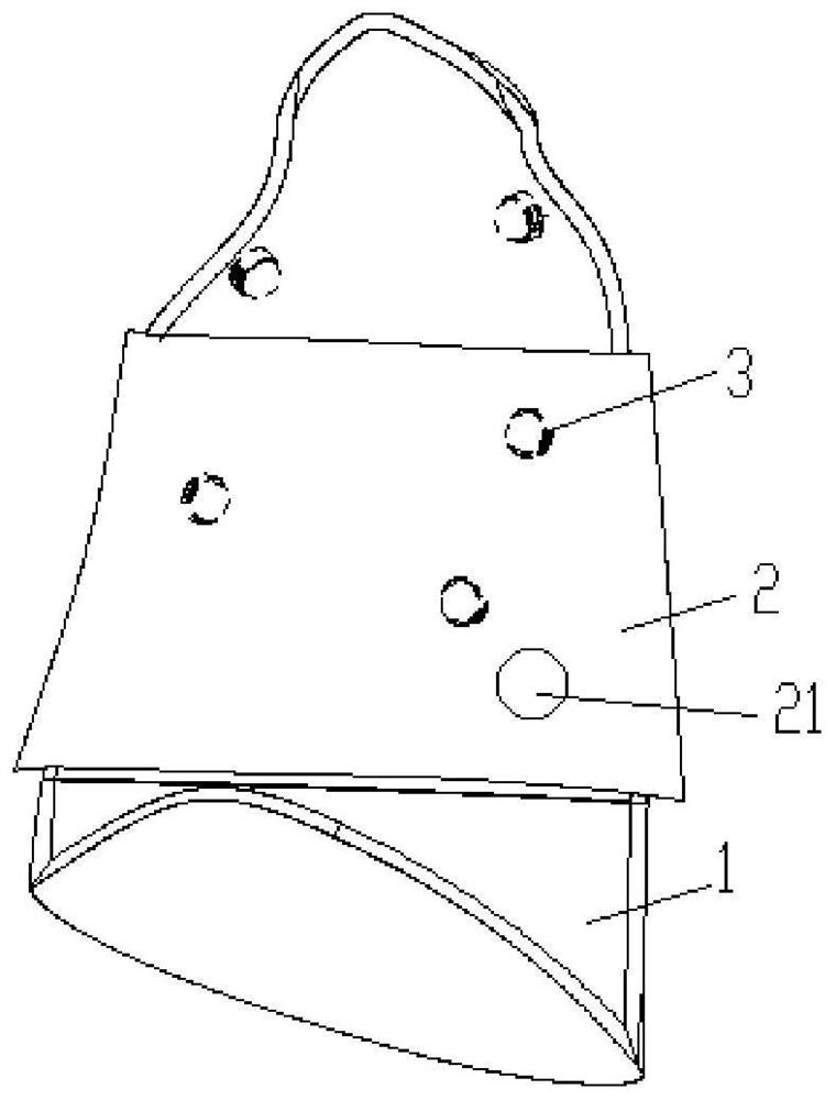
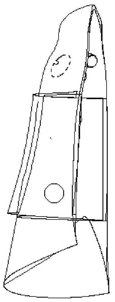
[0031] Such as figure 1 As shown, it is a schematic structural diagram of the holographic thoracoscope system provided by the present invention, such as Figure 2a , Figure 2b As shown, they are perspective views of the image generation device and the flexible display device of the present invention at two angles on the chest cavity of the patient. It can be seen from the figure that the holographic thoracoscope system of the present invention includes: a plurality of image generation devices 3, which are respectively placed on the chest cavity For different parts of the inner wall of the thoracic cavity of endoscopic surgery patients, each image generating device provides illumination for the thoracic cavity and collects image information of the corresponding part in the thoracic cavity, and forms video data containing the ID of each image generating device; the positioning device 7 is used to determine each The position of each image generating device on the inner wall of ...


PUM


Abstract

The invention discloses a holographic thoracoscope system, which comprises a plurality of image generation devices which are respectively arranged at different parts of the inner wall of the thoracic cavity of a thoracoscope operation patient, and each image generation device provides illumination for the thoracic cavity, acquires image information of the corresponding part in the thoracic cavity and forms video data containing the ID of each image generation device; a positioning device is used for determining the position of each image generation device on the inner wall of the thoracic cavity of the patient; a receiving and processing device is used for receiving the video data sent by the plurality of image generation devices and synthesizing the plurality of video data according to the positions of the plurality of image generation devices on the inner wall of the thoracic cavity of the patient so as to obtain a three-dimensional image in the thoracic cavity of the patient; a flexible display device is used for being arranged on the outer wall of the thoracic cavity of a thoracoscopic surgery patient and displaying the three-dimensional image in the thoracic cavity obtained after processing of the receiving and processing device so that an operator can conduct thoracoscopic surgery operation through the three-dimensional image and operation instruments.

Description

technical field [0001] The invention relates to the technical field of medical devices, in particular to a holographic thoracoscope system. Background technique [0002] In recent years, with the popularity of low-dose spiral CT, the epidemiology and treatment of lung tumors have undergone major changes. More and more patients with early-stage lung cancer have been discovered, and these patients are more suitable for minimally invasive resection. Thoracoscopic technology has been developed for nearly 30 years since 1992 and has been perfected day by day. Its effect in the treatment of lung cancer is comparable to that of ordinary thoracotomy and was written into the NCCN guidelines as early as 2006. Traditional VATS includes three-port and four-port thoracoscopy. With the development of technology, single-port thoracoscopic surgery has gradually been used clinically in recent years because of its smaller trauma. In 2011, Spanish scholar Gonzales first reported single-port VA...

Claims


Application Information

Patent Timeline
Patent Type & Authority Applications(China)
IPC IPC(8): A61B17/00A61B90/00A61B90/30A61B34/10A61B34/20A61B90/50
CPCA61B17/00234A61B90/361A61B90/37A61B90/30A61B34/10A61B34/20A61B90/50A61B2017/00238A61B2034/105A61B2034/107A61B2034/108A61B2034/2051A61B2034/2065
Inventor 陈应泰李凤卫
Owner 北京航天总医院
Why Eureka
Try Eureka