Plesiochronous digital hierarchy low speed signal switching system digital phase-locked loop

A quasi-synchronous digital, hierarchical structure technology, applied in the direction of synchronous signal speed/phase control, digital transmission system, time division multiplexing system, etc., can solve the problems of incompatibility and increased cost.

Inactive Publication Date: 2004-01-21
NEC CORP
View PDF0 Cites 0 Cited by
  • Summary
  • Abstract
  • Description
  • Claims
  • Application Information

AI Technical Summary

Problems solved by technology

However, since the auxiliary loop is at the center frequency of the storage system and applies control pulses to frequency regulator 1 during operation, the steady-state phase error is not caused by the control pulses of the main loop
[0010] However, because the 1.5M and 2M DPLL circuits must be designed separatel

Method used


Image

  • Plesiochronous digital hierarchy low speed signal switching system digital phase-locked loop
  • Plesiochronous digital hierarchy low speed signal switching system digital phase-locked loop
  • Plesiochronous digital hierarchy low speed signal switching system digital phase-locked loop

Examples


Embodiment Construction

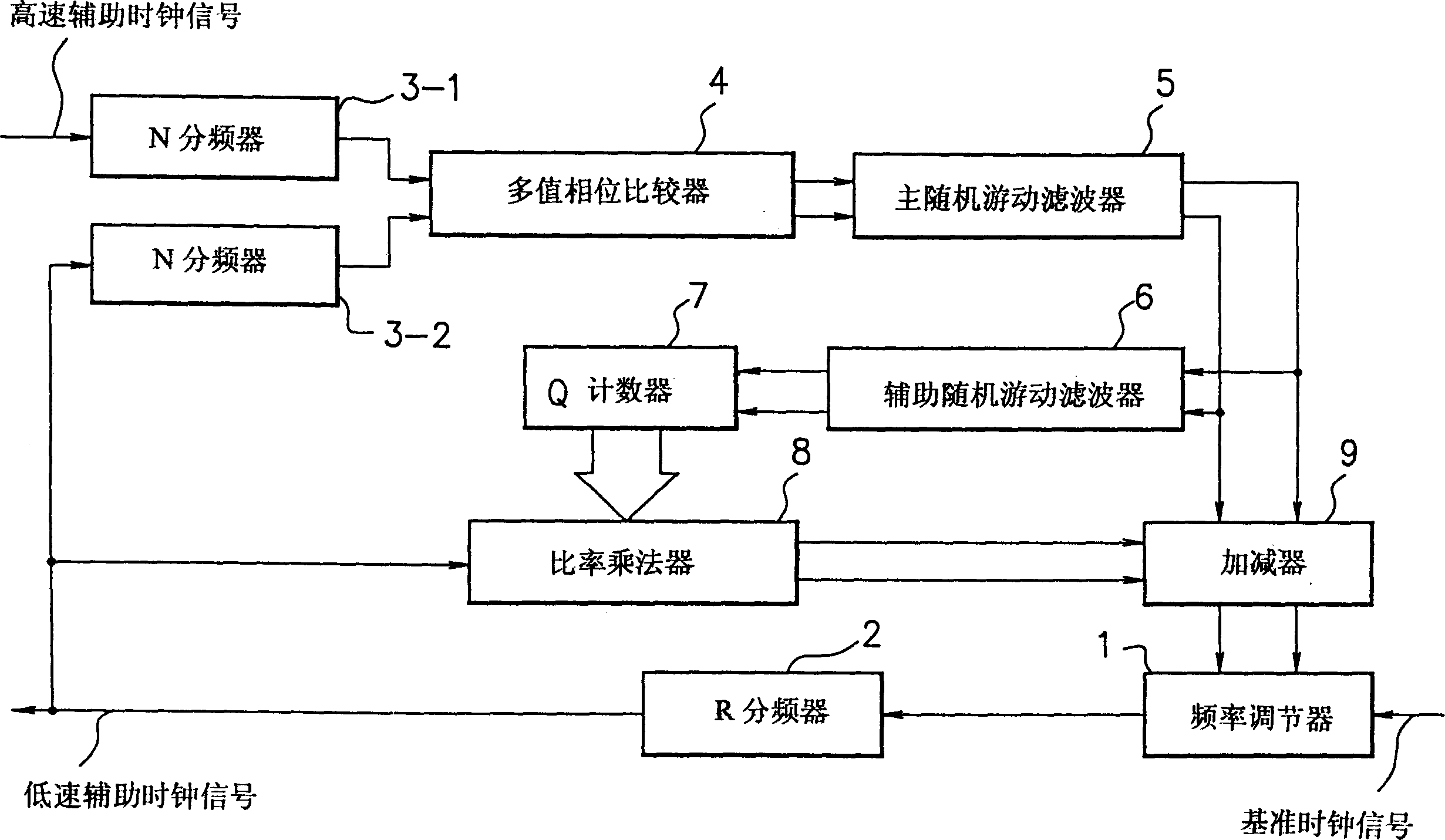
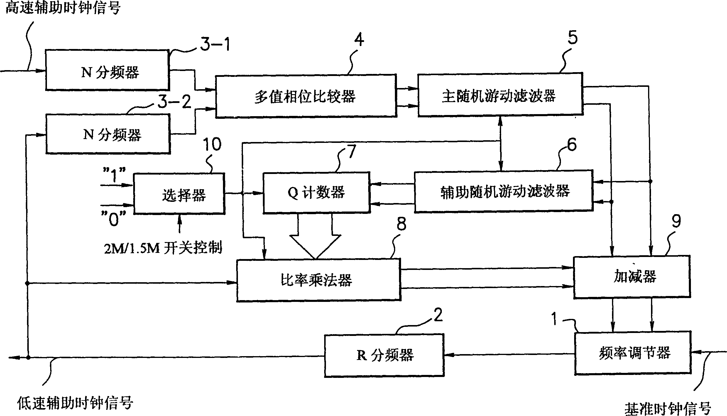
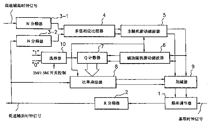
[0017] The following are the preferred embodiments of the present invention. The preferred embodiment of the present invention is a cleanup circuit using a full auxiliary system DPLL, which enables the main random walk filter ( figure 2 5 in ), the auxiliary random walk filter ( figure 2 6 in), a Q counter ( figure 2 7) of counting stages and ratio multipliers ( figure 2 8) in the ratio length will be based on the selector ( figure 2 In 10) the conversion signal changes, so that a required DPLL (digital phase-locked loop) circuit for various PDH low-speed signal interfaces can be obtained.

[0018] According to the embodiment of the present invention, the counter value for determining the system parameters of the DPLL (Digital Phase Locked Loop) can be set to the respective parameters of the 2M interface and the 1.5M interface by switching through the selector. It is not necessary to separately design DPLL circuits suitable for 2M cards and 1.5M cards. The operation ...


PUM


Abstract

A destuff circuit using a complete secondary system DPLL enables a DPLL circuit applicable to PDH low speed signal interface unit of a transmission communication apparatus to be shared. A switching signal from a selector causes a primary random walk filter, a secondary random walk filter, and counter number of a Q counter to be changed, and also causes the rate length of a rate multiplier, thereby providing a required DPLL circuit for a respective PDH low speed signal interface.

Description

technical field [0001] The present invention relates to receive cleanup circuits used in SDH (Synchronous Digital Hierarchy) networks. In particular the invention relates to a fully assisted DPLL (Digital Phase Locked Loop) used for synchronous stuffing in SDH networks. Background technique [0002] In the aspect of SDH (Synchronous Digital Hierarchy) network, the method of byte-filled pointer arithmetic is used, that is, the frequency adjustment method of high-speed auxiliary clock. That is, a fill pulse is filled at the data transmit end and a fill pulse is cleared at the receive end. The transmitted data is temporarily stored in the memory of the data receiving end, and then read out with the low-speed signal of the data receiving end. [0003] A discrepancy due to byte stuffing may occur in pointer arithmetic. Each pointer operation will form a difference of 8 [UI / time]. To obtain a low-speed clock signal from a high-speed clock signal, the phase difference generated...

Claims


Application Information

Patent Timeline
IPC IPC(8): H03L7/06H03L7/089H03L7/099H04J3/07H04L7/00H04L7/033
CPCH03L7/089H03L7/0993H04J3/076
Inventor 伊藤雅朗
Owner NEC CORP
Why Eureka
Try Eureka