Ship segmented spraying robot based on visual guidance

A spraying robot, vision-guided technology, applied in the directions of manipulators, spraying devices, liquid spraying devices, etc., to achieve the effect of increasing the vision-guided function

Inactive Publication Date: 2021-11-02
南通大学技术转移中心有限公司
View PDF10 Cites 8 Cited by
  • Summary
  • Abstract
  • Description
  • Claims
  • Application Information

AI Technical Summary

Problems solved by technology

[0008] The object of the present invention is to provide a kind of ship segmentation spraying robot based on visual guidance, to solve the problems mentioned in the above-mentioned background technology

Method used


Image

  • Ship segmented spraying robot based on visual guidance
  • Ship segmented spraying robot based on visual guidance
  • Ship segmented spraying robot based on visual guidance

Examples


Embodiment 1

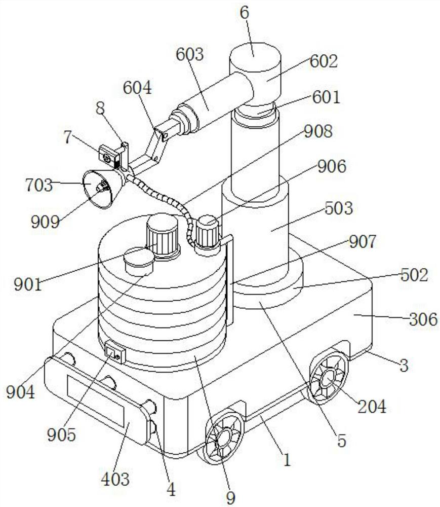
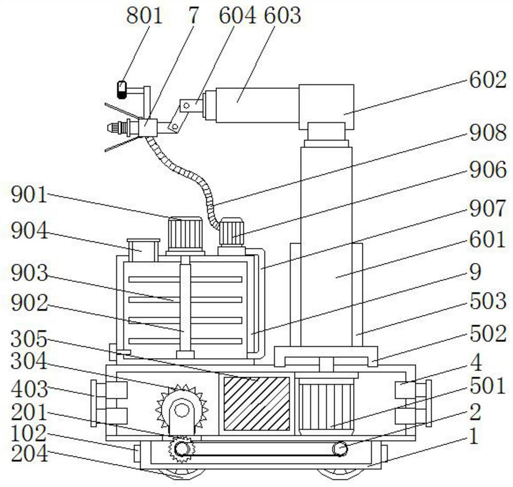
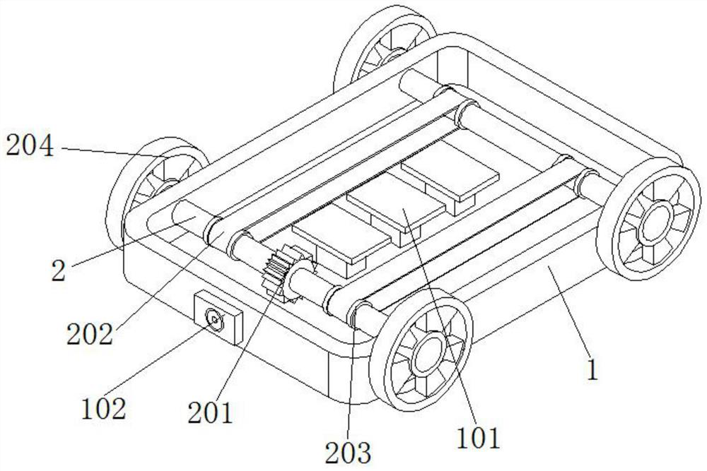
[0039] Such as figure 1 , figure 2 , image 3 and Figure 4 As shown, a vision-guided marine segmental spraying robot includes a bottom frame 1, a rotating rod 2 and a bottom plate 3. Two groups of rotating rods 2 arranged side by side are installed on the front of the bottom frame 1, and the back of the rotating rod 2 Through the inside of the bottom frame 1, a bottom plate 3 is installed on the top of the bottom frame 1, and a cover frame 306 is installed on the top of the bottom frame 3. A cylinder 4 is installed on both inner walls of the cover frame 306, and one end of the cylinder 4 extends out of the cover. the interior of box 306;

[0040] Specifically, the bottom frame 1 is used to integrate the components installed on the top of its inner box, so that the components interact with each other, the rotating rod 2 can be used for the rotational force, and the bottom plate 3 is used to block the top of the bottom frame 1, so that its interior It forms an independent ...

Embodiment 2

[0050] Such as Figure 8 As shown, the outer surface of the connecting column 7 is equipped with a threaded ring 701, the outer surface of the threaded ring 701 is threaded with an engaging ring 702, and one side of the outer wall of the engaging ring 702 is equipped with a cover plate 703, and the cover plate 703 is installed around the spray coating. The outside of the head 909.

[0051]Specifically, the thread of the threaded ring 701 can be consistent with the internal thread of the connecting ring 702, and the worker can hold the cover plate 703, align it with the connecting column 7 as a whole combined with the connecting ring 702, and then apply rotation to it. Power, impels the inner thread of the connecting ring 702 to fit with the threaded ring 701, which can facilitate the installation of the cover plate 703 on the outside of the spraying head 909. During the spraying operation, it can be used to block the spraying range and avoid spraying from the spraying head 909...

Embodiment 3

[0053] Such as Figure 7 As shown, an inverted L-shaped fixed rod 8 is installed on the top of the connecting column 7 , and a camera 801 is installed at one end of the inverted L-shaped fixed rod 8 , and the camera 801 is located above the cover plate 703 .

[0054] Specifically, the inverted L-shaped fixed rod 8 is used to install the camera 801. The camera 801 has functions such as taking pictures and recording videos. It is located above the spraying head 909. When the spraying head 909 is driven by the movable structure 6 to spray from bottom to top The area to be sprayed can be photographed by the camera 801 first, and then the photographed picture is transmitted to the processing component 305 electrically connected to it, and the processing component 305 judges whether spraying is possible.


PUM


Abstract

The invention discloses a ship segmented spraying robot based on visual guidance. The ship segmented spraying robot based on visual guidance comprises a bottom frame, rotating rods and a bottom plate, two rotating rods arranged side by side are installed on the front face of the bottom frame, the bottom plate is installed at the top of the bottom frame, a cover frame is installed at the top of the bottom plate, and cylinders are installed on the inner walls of the two sides of the cover frame; and a storage cylinder is installed at the top of the cover frame, a stirring motor is installed at the top of the storage cylinder, a rotating shaft is installed at the output end of the stirring motor, the bottom of the rotating shaft extends into the storage cylinder, a movable rod is installed at the bottom of the rotating shaft, and a plurality of stirring rods which are arranged up and down are uniformly installed on the outer surface of the movable rod. According to the ship segmented spraying robot based on visual guidance, paint supply can be conducted in real time, spraying can be shielded through the cover plate during spraying operation, the situation that the spraying operation exceeds the area range is avoided, meanwhile, segmented spraying operation can be conducted through the device, and when the robot is impacted, impact force can be absorbed through a telescopic spring, and then damage caused by impact is reduced.

Description

technical field [0001] The invention relates to the technical field of spraying robots, in particular to a segmental spraying robot for ships based on vision guidance. Background technique [0002] The outer surface of the ship needs to be sprayed with specific paint, and then change the appearance of the ship, and at the same time play a certain role in protecting the ship, preventing its outer surface from being eroded by sea water or river water, and then prolonging the service life of the ship. With the development of modern science and technology With gradual development, spraying robots are usually used in spraying operations at this stage to replace previous manual operations, which saves manpower and improves spraying efficiency. [0003] The defective that existing device exists is: [0004] 1. The comparative document CN108580092A discloses a spraying robot, "comprising a base, the bottom of the base is fixedly equipped with universal wheels, the right side of the...

Claims


Application Information

Patent Timeline
Patent Type & Authority Applications(China)
IPC IPC(8): B05B9/04B05B12/08B05B12/12B05B12/32B05B12/36B05B15/14B05B15/25B25J11/00
CPCB05B9/0403B05B15/25B05B12/081B05B12/12B05B15/14B05B12/32B05B12/36B25J11/0075
Inventor 陈聪
Owner 南通大学技术转移中心有限公司
Why Eureka
Try Eureka