Cascade flow regulation pump power energy-saving method
A technology of flow regulation and pump power, which is applied to components, pumps, and pump components of pumping devices for elastic fluids. The effect of resource waste, stable pressure, and stable water supply effect
- Summary
- Abstract
- Description
- Claims
- Application Information
AI Technical Summary
Problems solved by technology
Method used
Image
Examples
Embodiment 1
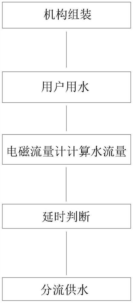
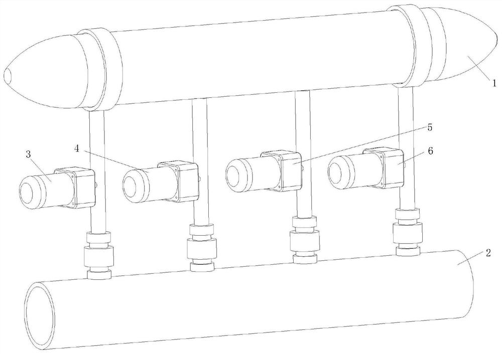
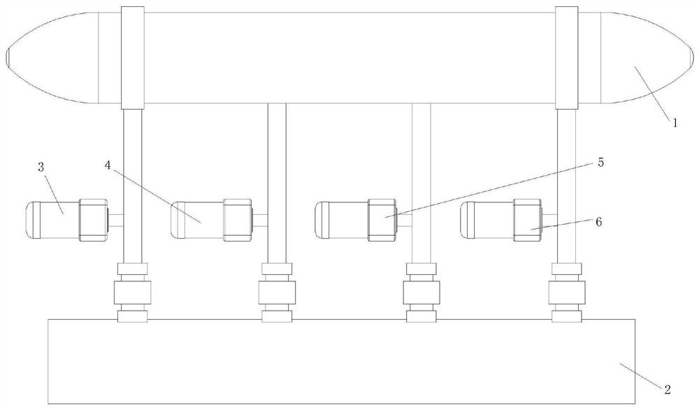
[0037] see Figure 1-3 , a cascade flow regulation pump power saving method, comprising the following steps:
[0038] Step A: Mechanism assembly, the mechanism includes water tank 1, user water supply pipeline 2, pump A3, pump B4, pump C5 and pump D6, four shunt pipes are connected between water tank 1 and user water supply pipeline 2, pump A3, pump B4, Pump C5 and pump D6 are respectively connected to four distribution pipes, and pump A3, pump B4, pump C5 and pump D6 are respectively connected to user water supply pipeline 2, and pump A3, pump B4, pump C5 and pump D6 have a design flow rate of 60 m3 / 11KW, 7.5KW, 3.0KW and 1.1KW under the water supply environment with a head of 90 meters and 90 meters head respectively, and the end of the user water supply pipe 2 is connected with an electromagnetic flowmeter that can extract instantaneous flow and total flow;
[0039] Step B: The user uses water, the equipment is started, and a pump of 7.5KW is started according to the conv...
Embodiment 2
[0053] refer to Figure 1-2 , in this embodiment, it is basically the same as Embodiment 1. What is more optimized is that in step A, the lifts of pump A5, pump B6, pump C7 and pump D8 in a water supply environment with a design flow rate of 60 cubic meters per hour and a lift of 90 meters The same is 90 meters, and the flow rate of single pump accounts for the total flow rate of pump A5: 75% (45 cubic meters / hour); pump B6: 45% (25 cubic meters / hour); pump C7: 25% (15 cubic meters / hour) ;Pump D8: 10% (6 cubic meters / hour), effectively avoiding that in the case of one pump being damaged, the water supply can still meet the basic water supply design requirements in accidents, that is, when the largest pump fails (extremely unfavorable), the rest of the pumps The total flow reaches 80% of the design flow.
Embodiment 3
[0055] In step D, the motor models corresponding to pump A3, pump B4, pump C5, and pump D6 are YE2-160M-4, YE2-132M-4, YE2-100L2-4, and YE2-90S-4 respectively. Working together, compared with the operation of three 7.5kw motors, the required energy loss of the motors is greatly reduced, making the device more energy-saving.
[0056] step four
[0057] The motor output power of pump A3, pump B4, pump C5 and pump D6 is proportional to the cube of the speed, then: Among them, P1: the power of the motor at power frequency, P2: the power of the motor at variable frequency; N1: the speed of the motor at power frequency, N2: the speed of the motor at variable frequency, the power consumption of each water interval can be directly calculated through the formula.
PUM
 Abstract
Description
Claims
Application Information
 - R&D
- Intellectual Property
- Life Sciences
- Materials
- Tech Scout
- Unparalleled Data Quality
- Higher Quality Content
- 60% Fewer Hallucinations
Browse by: Latest US Patents, China's latest patents, Technical Efficacy Thesaurus, Application Domain, Technology Topic, Popular Technical Reports.
© 2025 PatSnap. All rights reserved.Legal|Privacy policy|Modern Slavery Act Transparency Statement|Sitemap|About US| Contact US: help@patsnap.com


