Main shaft for scroll compressor and scroll compressor with main shaft

A scroll compressor and spindle technology, applied in the field of scroll compressors, can solve problems such as inability to lubricate and cool, affect the precision of the spindle, and make the process difficult, so as to improve the effect of lubrication and cooling, improve space utilization, and compact The effect of internal structure

Active Publication Date: 2021-11-02
靖江佳尔福科技有限公司
View PDF6 Cites 1 Cited by
  • Summary
  • Abstract
  • Description
  • Claims
  • Application Information

AI Technical Summary

Problems solved by technology

[0003] The principle of the scroll compressor is that there are two dynamic and static scrolls with double-function equation lines meshing with each other. During the working process of suction, compression and exhaust, the static scroll is fixed on the frame. The movable scroll is driven by the main shaft and restricted by the anti-rotation mechanism. It rotates in a plane with a small radius around the center of the base circle of the static scroll. The main shaft is driven by the motor and the rotor. Due to the characteristics of the scroll compressor, the scroll compression The main shaft of the machine rotates at high speed when it is working. High-speed rotation is prone to overheating. Overheating may cause damage to internal parts and excessive noise.
[0004] At present, there are very few solutions for the lubrication and cooling of the internal parts of the scroll compressor. The main technical solutions are: the rotating main shaft is composed of a straight shaft and an eccentric shaft. An oil channel is set inside to guide the medium oil for lubrication and cooling. The process is difficult and will affect the accuracy of the main shaft, and the eccentric shaft generally has a large diameter. If it is applied to a scroll compressor, the scroll compressor requires high precision of the main shaft. , the main shaft rotates at high speed, the medium oil cannot form an oil layer as expected to protect the main shaft and eccentric device, and it cannot lubricate and cool other parts inside the scroll compressor

Method used


Image

  • Main shaft for scroll compressor and scroll compressor with main shaft
  • Main shaft for scroll compressor and scroll compressor with main shaft
  • Main shaft for scroll compressor and scroll compressor with main shaft

Examples


Embodiment 1

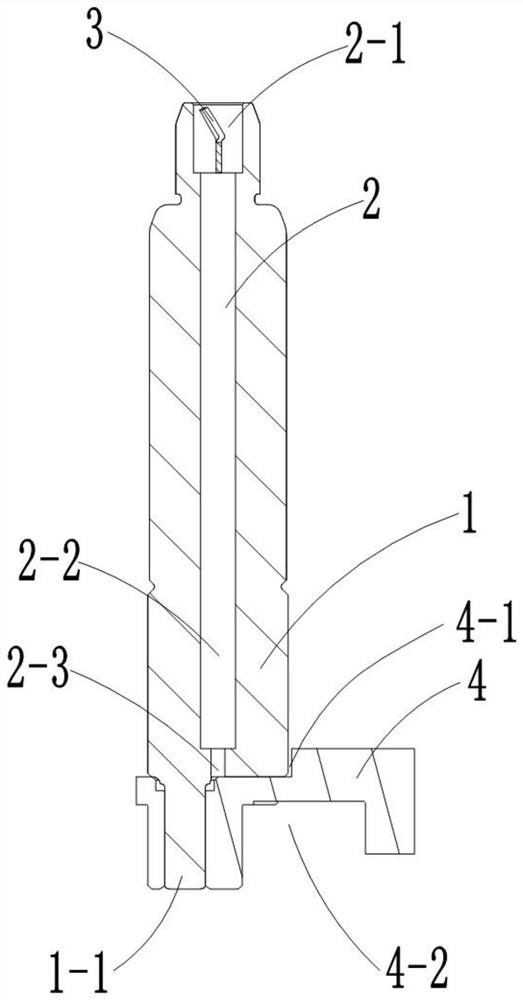
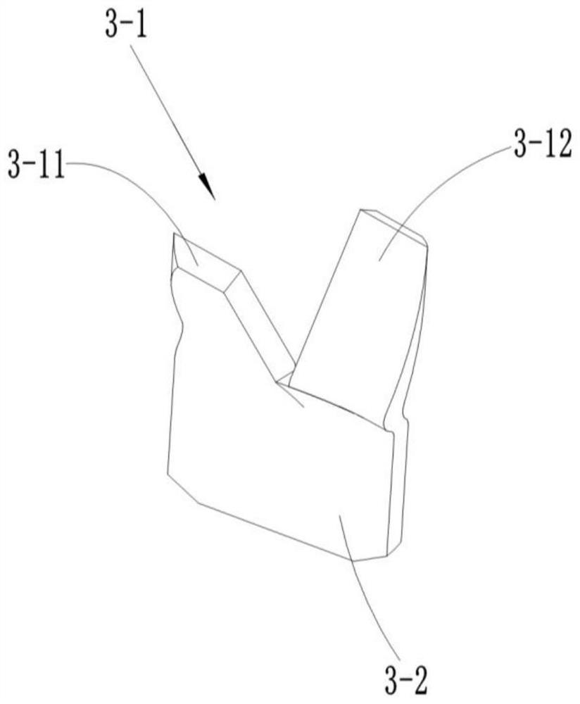
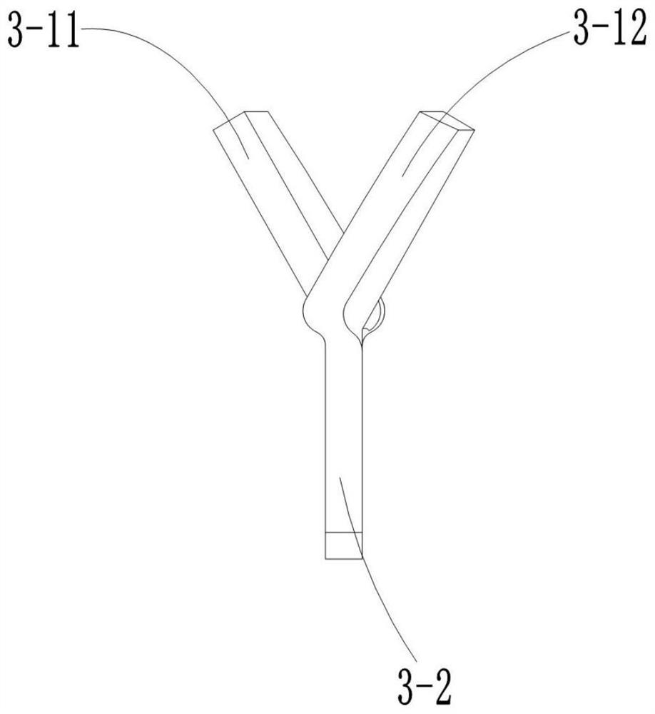
[0035] A main shaft for a scroll compressor, comprising a main shaft body 1, an oil guide channel 2 axially penetrating through the main shaft body 1 is arranged in the main shaft body 1, and the oil guide channel 2 is composed of a first oil guide channel 2-1, a second oil guide channel The channel 2-2 and the third oil guide channel 2-3 are connected in sequence, and the axes of the first oil guide channel 2-1, the second oil guide channel 2-2 and the third oil guide channel 2-3 are aligned with the spindle body The axes of 1 are coincident, the third oil guide channel 2-3 runs through the tail end of the main shaft body 1, the diameter of the first oil guide channel 2-1 is larger than the diameter of the second oil guide channel 2-2, and the second oil guide channel 2- The diameter of 2 is larger than the diameter of the third oil guide channel 2-3, and the rotary vane 3 is clamped in the first oil guide channel 2-1, and the rotary vane 3 is connected by the rotary vane part...


PUM


Abstract

The invention provides a main shaft for a scroll compressor. The main shaft comprises a main shaft body (1) and is characterized in that an oil guide channel (2) penetrating through the main shaft body (1) is arranged in the main shaft body (1), an eccentric device (4) is fixedly arranged at the tail end of the main shaft body (1), an oil outlet of the oil guide channel (2) faces the surface of the eccentric device (4), and a rotary vane (3) is clamped in the oil guide channel (2). When the main shaft body (1) rotates, the rotary vane (3) rotates along with the main shaft body (1) so as to suck medium oil into the oil guide channel (2). The invention further provides the scroll compressor. The scroll compressor is provided with the main shaft for the scroll compressor, a static scroll plate (8), a dynamic scroll plate (9), a motor (10), a main bearing (11), an auxiliary bearing (6), a controller shell (5) and a cylinder body bearing (7). The main shaft for the scroll compressor is simple in structure, easy to operate, high in oil suction efficiency and capable of better lubricating and cooling internal parts of the scroll compressor.

Description

technical field [0001] The invention relates to the field of scroll compressor testing, in particular to a main shaft for a scroll compressor and a scroll compressor with the same. Background technique [0002] As the international issue of carbon neutrality and carbon peaking is raised, the country is also in line with international standards, and vigorously promotes energy-saving and environmental protection industries to achieve carbon neutrality and carbon peaking. New energy vehicles are an important part of the country's goal. The scroll compressor is a key component of new energy vehicles, so the performance of scroll compressors has a major impact on new energy vehicles. [0003] The principle of the scroll compressor is that there are two dynamic and static scrolls with double-function equation lines meshing with each other. During the working process of suction, compression and exhaust, the static scroll is fixed on the frame. The movable scroll is driven by the m...

Claims


Application Information

Patent Timeline
Patent Type & Authority Applications(China)
IPC IPC(8): F04C29/00F04C18/02F04C29/02F04C29/04
CPCF04C29/00F04C29/04F04C29/023F04C18/0215F04C2240/603
Inventor 不公告发明人
Owner 靖江佳尔福科技有限公司
Why Eureka
Try Eureka