Method for identifying crack area of space balance truss plate girder
A technology of area identification and truss plate, applied in special data processing applications, complex mathematical operations, instruments, etc., can solve the problems of lack, large plate beams are bulky, plate beams are prone to cracks, etc., and achieve the effect of convenient strength
- Summary
- Abstract
- Description
- Claims
- Application Information
AI Technical Summary
Problems solved by technology
Method used
Image

Examples
Embodiment 1
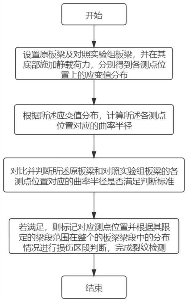
[0034] refer to Figure 1~3 , which is an embodiment of the present invention, provides a method for identifying a crack region of a space-balanced truss plate girder, including:
[0035] S1: Set up the original slab girder and the slab girder of the control experiment group, and apply a static load force at the bottom to obtain the distribution of strain values at each measuring point;
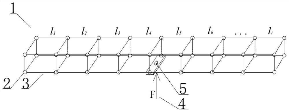
[0036] Specifically, the original space balance truss slab girder is defined to have the same structural properties as the control experiment group slab girder, and its parameter properties and constraint conditions must be consistent to reduce errors. is o), the nodes with the same distance from the center of the circle are grouped into one group, and the original plate girder and the reference plate girder are divided into the same number and the same size according to the longitudinal dimension between the corresponding measuring points of each group and the neutral axis of the beam sectio...
Embodiment 2
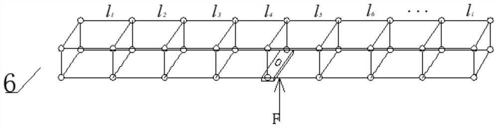
[0053] refer to Figure 4 It is another embodiment of the present invention. In order to verify and illustrate the technical effect adopted in this method, this embodiment uses a traditional technical solution to carry out a comparative test with the method of the present invention, and compares the test results by means of scientific demonstration to verify that the method has real effect.
[0054] Traditional technical solution: In plate girder testing, the mid-span section of the hollow beam is used as the stress test section, and two stress measuring points are arranged on both sides of the upper and lower edges of the section, and two ground anchors are placed at both ends of the beam , a jack is arranged in the mid-span section of the beam, and the deflection of the mid-span section and the bending stress change of the upper and lower edges are analyzed. The disadvantages of traditional technical solutions are:
[0055] (1) The observation technology for the cracks and...
PUM
 Abstract
Description
Claims
Application Information
 - R&D
- Intellectual Property
- Life Sciences
- Materials
- Tech Scout
- Unparalleled Data Quality
- Higher Quality Content
- 60% Fewer Hallucinations
Browse by: Latest US Patents, China's latest patents, Technical Efficacy Thesaurus, Application Domain, Technology Topic, Popular Technical Reports.
© 2025 PatSnap. All rights reserved.Legal|Privacy policy|Modern Slavery Act Transparency Statement|Sitemap|About US| Contact US: help@patsnap.com