
Low-voltage transformer area load non-power-cut switching system and working method thereof

A low-voltage station area and switching system technology, applied in the direction of power network operating system integration, information technology support systems, electrical components, etc., can solve problems affecting system stability, increase live working steps and safety risks, and safety shackles, etc., to achieve Improve reliability and safety, simplify live working steps, and increase the effect of application scenarios

Active Publication Date: 2021-11-02
HANGZHOU ELECTRIC EQUIP MFG +2
View PDF4 Cites 2 Cited by
  • Summary
  • Abstract
  • Description
  • Claims
  • Application Information

AI Technical Summary

Problems solved by technology

[0003] At present, in the 0.4kV low-voltage system, the scheme of realizing the reverse power between the mains and the generator by checking the synchronization first and then switching has been applied, but its disadvantages are described as follows: First, this scheme requires the paralleling of the generator and the grid Grid operation will have a greater impact on the generator and grid, which will affect the stability of the system, and even cause the risk of grid failure and failure
Secondly, in order to simplify the operation steps of grid connection, it is necessary to perform bypass power supply operation on the grid side. In addition to the live operation on the outlet end of the grid side, the live operation on the input end of the grid side is also required, which increases the live operation steps and safety risks.
In addition, there are obvious differences in the way of backup power supply in various places. For example, the backup power supply uses a mobile box transformer. At this time, due to the difference in the wiring mode of the transformer and the difference between the full load and no-load of the two power supplies, the frequency of the two power supplies on the low-voltage side is the same, but Due to the large angle difference, the requirements for grid connection cannot be met at this time, resulting in the inability to realize load switching through synchronization check and grid connection, thus failing to meet the needs of all users
[0004] In order to solve the safety shackles in the existing quasi-synchronous grid connection from the perspective of technological innovation, further simplify the live working steps, increase the application scenarios of uninterrupted operation, and improve the reliability and safety of uninterrupted switching, a new type of uninterrupted switching is urgently needed solution, so as to realize the smooth transition of the load without power failure

Method used


Image

  • Low-voltage transformer area load non-power-cut switching system and working method thereof
  • Low-voltage transformer area load non-power-cut switching system and working method thereof
  • Low-voltage transformer area load non-power-cut switching system and working method thereof

Examples


Embodiment Construction

[0047] The technical solutions of the present invention will be further described in detail below with reference to the accompanying drawings.

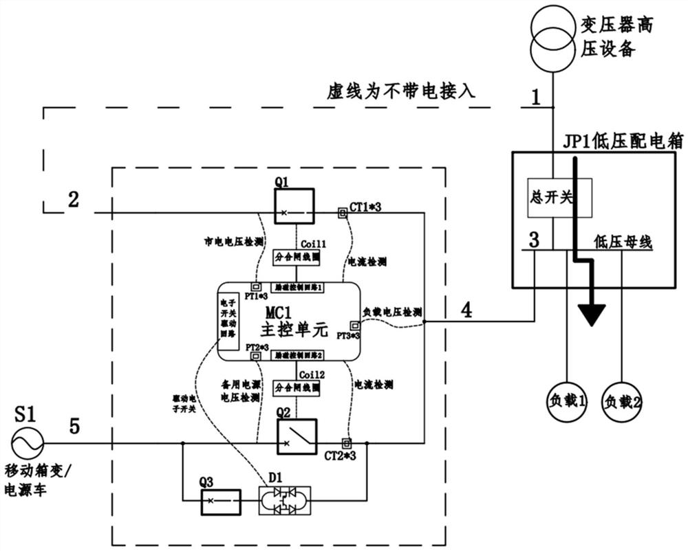
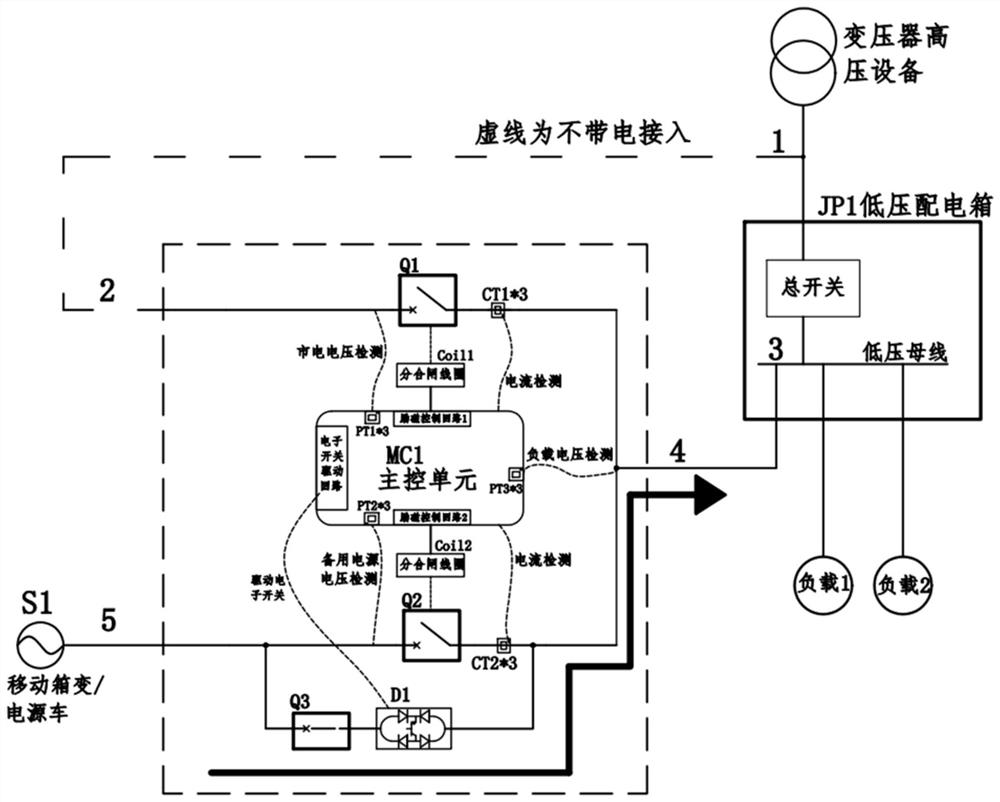
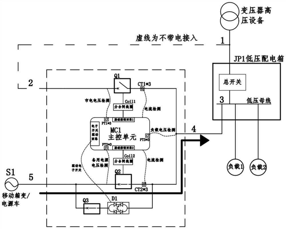
[0048] like figure 1 As shown, the present invention mainly includes a primary conductive branch, a short-time conductive branch, a market electrolyte, a control circuit, and a current / voltage signal acquisition module;

[0049] Where: the primary electric branch includes a second circuit breaker Q2; one end of the second circuit breaker Q2 is connected to the moving box change / power vehicle S1; the other end of the second circuit breaker Q2 is connected to the low voltage distribution box JP1;

[0050] The short-time conductive branch includes an electron solid state switch D1 and a first circuit breaker Q1; short-time conductive branch and the second circuit breaker Q2 are parallel;

[0051] The main circuit bypass includes a first circuit breaker Q1; one end of the first circuit breaker Q1 is connected to the low voltage distributi...


PUM


Abstract

The invention discloses a low-voltage transformer area load non-power-cut switching system and a working method thereof, and relates to the technical field of electric power operation, maintenance and power supply. At present, power-off switching is needed during power grid maintenance. The system comprises a main conductive branch, a short-time conductive branch, a commercial power bypass, a control circuit and a current / voltage signal acquisition module. The main conductive branch comprises a second circuit breaker Q2; one end of the second circuit breaker Q2 is connected with the mobile box transformer substation / power van S1, and the other end of the second circuit breaker Q2 is connected with the wire outlet end of the low-voltage distribution box JP1; the short-time conductive branch comprises an electronic solid-state switch D1; the short-time conductive branch is connected in parallel with the second circuit breaker Q2; the commercial power bypass comprises a first circuit breaker Q1; and one end of the first circuit breaker Q1 is connected with the wire outlet end of the low-voltage distribution box JP1, and the other end of the first circuit breaker Q1 is connected with the wire inlet end of the low-voltage distribution box JP1. According to the technical scheme, the solid-state electronic solid-state switch D1 bears the transient process, the short-time power failure phenomenon caused by breaking of a mechanical contact is avoided, and therefore non-power-cut switching of the load between the power grid and the standby power supply is achieved.

Description

Technical field [0001] The present invention relates to the field of electricity inspection power supply, and more particularly to a low pressure station region load non-power-on switching system and its working method. Background technique [0002] Low-voltage distribution network for user access, defect processing, equipment checking, maintenance, accident processing, and superior grid maintenance needs, often uses the first-stop-powered method, causing more power failure, longer, seriously affected The company's normal production is also inconvenient to bring people life. The power supply company himself also reduced the amount of electricity consumption due to power failure, which undertakes the responsibility of complaints caused by frequently power outages due to users in the jurisdiction, and harm the social image of power supply enterprises, so the social impact caused by the power outage is highly valued by power supply. [0003] At present, in the 0.4 kV low voltage sys...

Claims


Application Information

Patent Timeline
Patent Type & Authority Applications(China)
IPC IPC(8): H02J9/06H02J3/38H02J3/42
CPCH02J9/06H02J9/068H02J3/381H02J3/42Y02B70/30Y04S20/20
Inventor 夏军强陈运孔仪潇谢赟朱华锋赵国庆毛钥能
Owner HANGZHOU ELECTRIC EQUIP MFG
Learn More