Frequency-adjustable condenser microphone head damping mechanism
A technology of condenser microphone and shock-absorbing mechanism, which is applied in the direction of microphone mouth/microphone accessories, etc., and can solve problems such as component damage and microphone head damage
- Summary
- Abstract
- Description
- Claims
- Application Information
AI Technical Summary
Problems solved by technology
Method used
Image
Examples
Embodiment 1
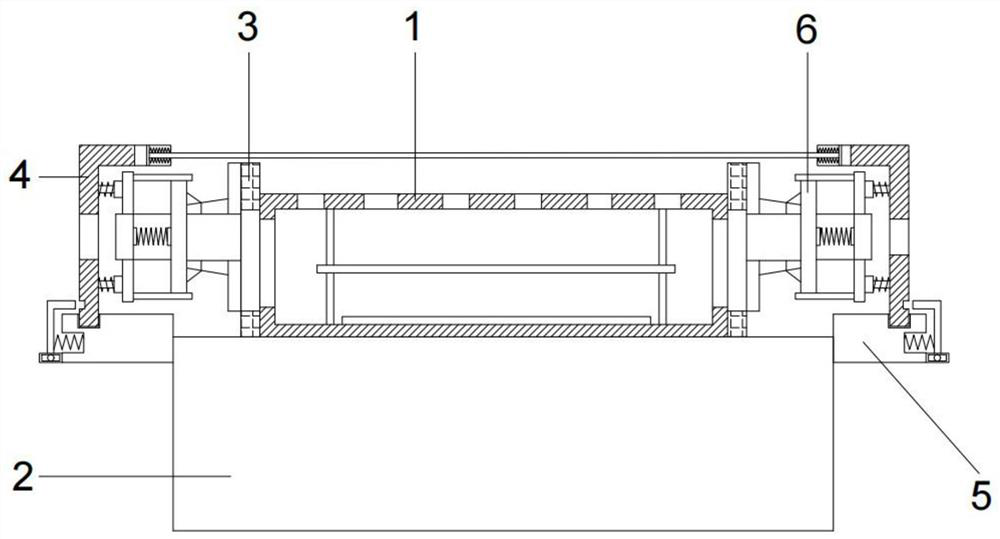
[0037] Embodiments of the present invention provide an adjustable frequency capacitive microphone microphone head damping mechanism, such as figure 1 As shown, it includes a microphone, and the microphone includes a microphone main body 1 and a microphone base 2, the microphone main body 1 is arranged inside the protective cover 3, and the protective cover 3 is arranged on the upper end of the microphone base 2, The lower end of the microphone main body 1 is connected with a microphone base 2, and the left and right sides of the protective cover 3 are symmetrically connected with a shock absorbing mechanism 6, and the shock absorbing mechanism 6 is connected with a dustproof cover 4, and the dustproof cover 4 is connected with the microphone base 2 through a detachable mechanism.
[0038] The beneficial effect of above-mentioned technical scheme is:
[0039] The microphone main body 1 is set inside the protective cover 3 to protect the microphone main body 1. The lower end of...
Embodiment 2
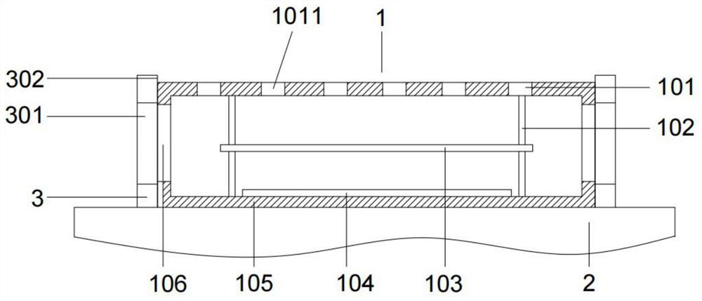
[0041] On the basis of above-mentioned embodiment 1, as figure 2 As shown, the microphone main body 1 is a capacitive microphone, and the microphone main body 1 includes a metal sheet 101, and the metal sheet 101 is uniformly arranged with a plurality of sound pickup holes 1011 in the circumferential direction, and the lower end of the metal sheet 101 is elastically The rod 102 is fixedly connected with the circuit board 105, and the elastic rod 102 is symmetrically arranged on the left and right sides between the metal sheet 101 and the circuit board 105, and the middle part of the elastic rod 102 on the left and right sides is fixedly connected with a film 103, so The circuit board 105 is connected with a frequency modulation circuit, and the upper end of the circuit board 105 is provided with a conductive part 104;
[0042] The protective cover 3 is an elastic cover, and the left and right sides of the protective cover 3 are symmetrically provided with a vent one 301, and ...
Embodiment 3
[0046] On the basis of Example 2, such as Figure 4-Figure 5 As shown, the shock absorbing mechanism 6 includes a connecting plate 601, the shape of the end of the connecting plate 601 close to the protective cover 3 fits the shape of the protective cover 3, and the connecting plate 601 is far away from the One end of the protective cover 3 is fixedly connected to the first connecting block 611, and the first connecting block 611 is fixedly connected to the second connecting plate 603. The hinge seat 1 605 is symmetrically arranged on the upper and lower sides of the end of the third connecting plate 604 close to the second connecting plate 603 at the end far away from the connecting plate 2 603, and the end of the connecting plate 2 603 and the connecting plate 3 604 are close to each other A spring plate 1 606 and a spring plate 2 607 are symmetrically arranged on the front and rear sides, a spring 1 608 is arranged between the spring plate 1 606 and the spring plate 2 607, ...
PUM
 Abstract
Description
Claims
Application Information
 - R&D
- Intellectual Property
- Life Sciences
- Materials
- Tech Scout
- Unparalleled Data Quality
- Higher Quality Content
- 60% Fewer Hallucinations
Browse by: Latest US Patents, China's latest patents, Technical Efficacy Thesaurus, Application Domain, Technology Topic, Popular Technical Reports.
© 2025 PatSnap. All rights reserved.Legal|Privacy policy|Modern Slavery Act Transparency Statement|Sitemap|About US| Contact US: help@patsnap.com


