Chain wheel seat casting system

A technology of casting system and sprocket seat, which is applied in the direction of casting mold, casting mold composition, casting molding equipment, etc., and can solve the problems of sprocket seat shrinkage and loosening

Pending Publication Date: 2021-11-05
LAIZHOU HONGYUAN BENCH VICE MFR
View PDF0 Cites 0 Cited by
  • Summary
  • Abstract
  • Description
  • Claims
  • Application Information

AI Technical Summary

Problems solved by technology

[0004] Aiming at the technical problem that the existing casting system easily causes the spr

Method used


Image

  • Chain wheel seat casting system
  • Chain wheel seat casting system
  • Chain wheel seat casting system

Examples


Embodiment 1

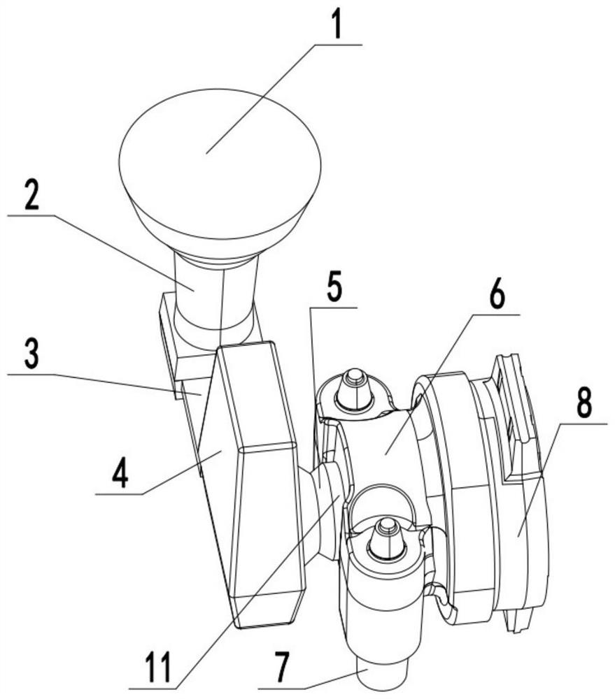
[0031] Please refer to figure 1 , Figure 4 , Figure 5 and Image 6 , a sprocket seat casting system, including a connected sprue cup 1, a sprue 2 and a runner 3, the sprue cup 1 is conical with a wide top and a narrow bottom, and the sprue 2 is a cylinder Body shape, the cross-section of the runner 3 is trapezoidal, the runner 3 extends between the sprue 2 and the dark riser 4, and the end of the runner 3 is provided with a dark riser 4 , the dark riser 4 communicates with the inner runner 5 at 90°, the inner runner 5 communicates with the casting cavity of the sprocket seat 6, and the joint between the inner runner 5 and the casting cavity It is the center hole 6-1 of the sprocket seat 6, and the height of the sprue cup 1 is greater than the height of the casting cavity, so as to ensure that the molten iron can smoothly fill the cavity. The dark riser 4 is a trapezoid with a narrow top and a wide bottom. At least one dark riser 4 is provided, and the inner runner 5 com...

Embodiment 2

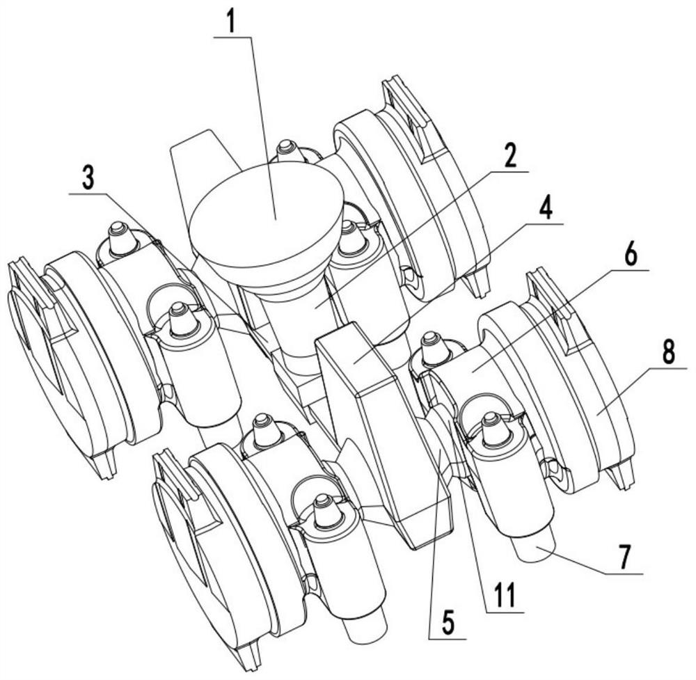
[0038] Please refer to figure 2 and image 3 , The difference from Example 1 is the number of dark risers 4, and the rest are the same as Example 1.

[0039] The sprue cup 1 is provided with one, and the runner 3 and the dark riser 4 are provided with two, and the two dark risers 4 and the runner 3 are arranged symmetrically on the side of the sprue cup 1 On both sides, both sides of the hidden riser 4 are provided with ingates 5, so the casting of four sprocket seats 6 can be completed in one casting, which greatly improves the casting efficiency.

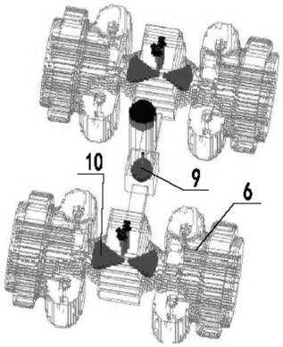
[0040] Please refer to image 3 After the design of the casting system is completed, the cooling process of the molten iron in the entire casting system is analyzed through CAE. There are only two shrinkage porosity in the entire casting system, which are shrinkage porosity 9 in the sprue and shrinkage porosity 10 in the inner runner. The pine is located outside the sprocket seat 6 , so the cast sprocket seat 6 has no shrinkag...


PUM


Abstract

The invention relates to the technical field of engineering machinery, in particular to a chain wheel seat casting system. The system comprises a pouring cup, a straight pouring gate and a transverse pouring gate which are communicated, a blind riser is arranged at the end of the transverse pouring gate and communicated with an inner pouring gate in a 90-degree angle, the inner pouring gate is communicated with a casting cavity of a chain wheel seat, and the joint of the inner pouring gate and the casting cavity is a center hole of the chain wheel seat. The inner pouring gate is in contact with the casting cavity at the center hole of the chain wheel seat, so that the inner pouring gate can be connected with the structure of the chain wheel seat in a 360-degree range, molten iron is ensured to be quickly injected into an upper cavity and a lower cavity of the casting cavity, sequential solidification is realized, the phenomenon of shrinkage porosity is avoided, and meanwhile, the separation part of the inner pouring gate and the cast chain wheel seat is positioned at the center hole, so that a casting head formed through separation can be removed in a drilling manner or a trepanning drilling manner, the trace of the casting head formed on the chain wheel seat is avoided, the quality of the chain wheel seat is improved, meanwhile, damage caused by manual polishing of the casting head is avoided, and the machining efficiency is improved.

Description

technical field [0001] The invention relates to the technical field of engineering machinery, in particular to a sprocket seat casting system. Background technique [0002] The sprocket seat is one of the important parts of crawler construction machinery, and it mainly plays the role of carrying the track. In addition to the material requirements for technical indicators, the most important thing is that shrinkage is absolutely not allowed inside the component material. Once shrinkage occurs, it will not only affect the strength of the parts, but more importantly, it will cause the leakage of the lubricating oil inside the seal, resulting in severe wear and tear of the parts, until they are scrapped. The most fundamental reason for the shrinkage of the sprocket seat is the sequential solidification of the pouring system. Due to the uneven thickness of the product structure and the unreasonable design of the casting system, the sprocket seat is prone to shrinkage after cast...

Claims


Application Information

Patent Timeline
IPC IPC(8): B22C9/08B22C9/24
CPCB22C9/082B22C9/088B22C9/24
Inventor 王忠全单学义蔡生杰候贺涛王树兴
Owner LAIZHOU HONGYUAN BENCH VICE MFR
Why Eureka
Try Eureka