
Construction method for cutting and crossing existing vertical shaft through multi-cavern underground excavation channel

A construction method and shaft technology, which are applied to shaft equipment, well sinking, tunnels, etc., to achieve the effect of improving construction efficiency, shortening construction period, and ensuring structural safety

Active Publication Date: 2021-11-05
CHINA RAILWAY LIUYUAN GRP CO LTD
View PDF8 Cites 0 Cited by
  • Summary
  • Abstract
  • Description
  • Claims
  • Application Information

AI Technical Summary

Problems solved by technology

[0003] In order to solve the above technical problems, the embodiment of the invention provides a construction method in which the multi-cavity underground excavation passage is cut through the existing shaft, which solves the problems of safety and construction period caused by the conflict between the multi-cavity underground excavation passage and the existing shaft, and ensures Improve construction safety and improve construction efficiency

Method used


Image

  • Construction method for cutting and crossing existing vertical shaft through multi-cavern underground excavation channel
  • Construction method for cutting and crossing existing vertical shaft through multi-cavern underground excavation channel
  • Construction method for cutting and crossing existing vertical shaft through multi-cavern underground excavation channel

Examples


Embodiment Construction

[0029] In order to enable those skilled in the art to better understand the technical solution of the present invention, the present invention will be described in detail below in conjunction with the accompanying drawings and specific embodiments.

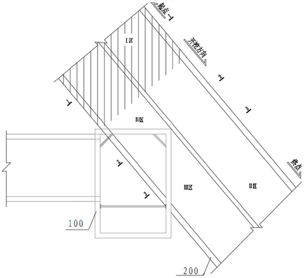
[0030] This embodiment also provides a construction method in which the multi-chamber underground excavation channel is cut through the existing shaft, such as Figure 1 to Figure 9 As shown, the method includes the following steps:

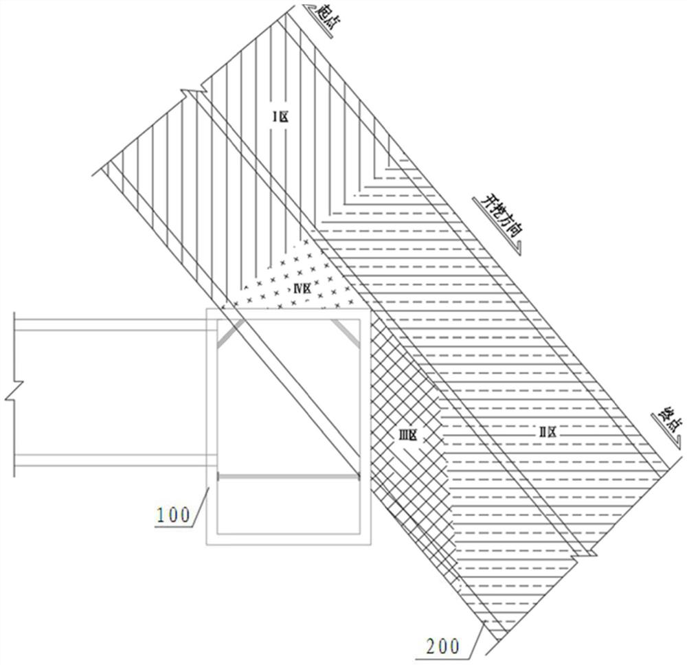
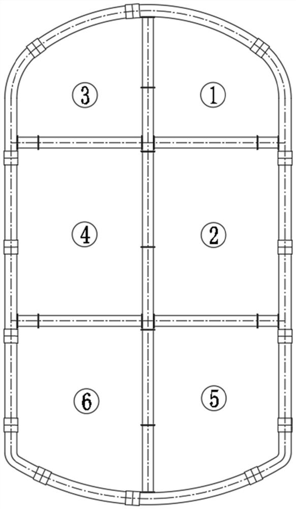
[0031] Step S1: First excavate the unaffected area (i.e. zone I) located in front of the existing shaft 100 to the skin of the existing shaft 100, temporarily close the tunnel face, and suspend excavation after the tunnel face is closed, such as figure 2 As shown; the excavation of multi-cavity submerged cross passage 200 adopts the CRD construction method, and the cross section of the cross passage is divided into six parts, arranged in three layers, left and right, and two columns. image 3 As sh...


PUM


Abstract

The invention provides a construction method for cutting and crossing an existing vertical shaft through a multi-cavern underground excavation channel. The construction method comprises the following steps that a multi-cavern underground excavation transverse channel is excavated to the outer skin of the existing vertical shaft, a tunnel face is closed temporarily, and excavation is paused after closing the tunnel face; a transverse channel part outside the influence area of the existing vertical shaft is excavated and cut until the transverse channel part is outside the influence area of the existing vertical shaft, then gradually excavating is achieved from the excavation part to another part in a horn mouth manner, and temporarily supporting the excavation part in the influence area by adopting profile steel is achieved; the profile steel at a horn mouth is broken in a closed annular channel, reversely excavating the part of the channel, which needs to cut the existing vertical shaft, until the outer skin of the existing vertical shaft, and supporting the position close to the outer skin of the existing vertical shaft by adopting the profile steel is achieved; and the remaining part between the transverse channel and the existing vertical shaft is constructed in a horn mouth excavation mode, and the transverse channel passes through the existing vertical shaft. According to the construction method for cutting and crossing the existing vertical shaft through the multi-cavern underground excavation channel, the problems of safety, construction period and the like caused by the conflict between the multi-cavern underground excavation channel and the existing vertical shaft are solved, the construction safety is ensured, and the construction efficiency is improved.

Description

technical field [0001] The invention belongs to the technical field of building structure engineering, and in particular relates to a construction method for cutting and crossing an existing vertical shaft through a multi-chamber underground excavation channel. Background technique [0002] The multi-cavity submerged channel is used as the construction channel of the subway station, or a permanent structural component of the subway station (such as air ducts, entrances and exits, etc.), and construction needs to be carried out according to the construction schedule. The existing shaft is used as an operation channel for the construction of the subway station, and it also needs to be used for operation according to the requirements of the construction period. At present, the application of underground excavation in the field of rail transit is gradually increasing. Under the premise that the ground conditions are relatively harsh and there is no open excavation construction, ...

Claims


Application Information

Patent Timeline
Patent Type & Authority Applications(China)
IPC IPC(8): E21D1/00E21D5/04E21D7/00E21D9/14
CPCE21D1/00E21D5/04E21D7/00E21D9/14Y02E10/20
Inventor 张金伟马铭泽徐骞唐云沙杨斌斌刘志广张美琴张存高菊英康宁李佳庆马文付黎龙程科徐斌李晓英李昂
Owner CHINA RAILWAY LIUYUAN GRP CO LTD
Learn More