Boiler feed water preheating device
A preheating device and boiler feed water technology, which is applied in the direction of feed water heaters, preheating, lighting and heating equipment, etc., can solve the problems of unadjustable flue gas emission efficiency and water heating efficiency, poor flue gas emission, and poor water heating effect Good and other problems, to achieve the effect of improving heat utilization, optimizing balance effect and saving fuel
- Summary
- Abstract
- Description
- Claims
- Application Information
AI Technical Summary
Problems solved by technology
Method used
Image

Examples
Embodiment
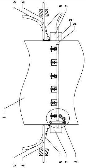
[0033] Example: as attached Figures 1 to 14 As shown, a boiler feed water preheating device includes a flue exhaust duct 1 extending in the upper and lower directions, and the cross section of the flue exhaust duct 1 is rectangular in shape. The inner side of the flue exhaust duct 1 is connected with several heating water tanks 25 driven by a rotating drive device. Specifically, several heating water tanks 25 are arranged along the left and right directions, and each heating water tank 25 is arranged along the front and rear directions. The shape of the water tank 25 is elongated. In the initial state, the heating water tank 25 is vertically arranged, and the thickness of the upper and lower side edges gradually decreases from the inside to the outside. When the heating water tank 25 deflects 90 degrees, two adjacent The gap between the edges of the part heating water tank 25 is smaller to reduce the passage of dust or smoke. Reduce dust.
[0034] Specifically, a rotating s...
PUM
 Abstract
Description
Claims
Application Information