
Relativistic electron beam transmission scheme design method, device, equipment and medium

A technology of transmission scheme and design method, which is applied in the field of relativistic electron beam transmission scheme design method, equipment and medium, and device, which can solve problems such as rising cost and complexity, difficult engineering application, inability to effectively carry out long-distance stable transmission, etc., to achieve Effects of suppressing filamentation instability and twist instability, improving stability, and reducing beam transmission loss

Active Publication Date: 2021-11-05
NAT UNIV OF DEFENSE TECH
View PDF4 Cites 1 Cited by
  • Summary
  • Abstract
  • Description
  • Claims
  • Application Information

AI Technical Summary

Problems solved by technology

[0003] The long-distance transmission of the relativistic electron beam has very high requirements for the collimation method of the electron beam. However, in the process of realizing the present invention, the inventors have found that common collimation methods such as magnetic quadrupole lenses and external magnetic fields are used in long-distance transmission. In this scenario, its cost and complexity have increased exponentially, engineering application is more difficult, and there are technical problems that cannot effectively carry out long-distance stable transmission

Method used


Image

  • Relativistic electron beam transmission scheme design method, device, equipment and medium
  • Relativistic electron beam transmission scheme design method, device, equipment and medium
  • Relativistic electron beam transmission scheme design method, device, equipment and medium

Examples


Embodiment Construction

[0028] In order to make the purpose, technical solution and advantages of the present application clearer, the present application will be further described in detail below in conjunction with the accompanying drawings and embodiments. It should be understood that the specific embodiments described here are only used to explain the present application, not to limit the present application.

[0029] Unless otherwise defined, all technical and scientific terms used herein have the same meaning as commonly understood by one of ordinary skill in the technical field to which this application belongs. The terms used herein in the specification of the application are only for the purpose of describing specific embodiments, and are not intended to limit the application.

[0030] In addition, the technical solutions of the various embodiments of the present invention can be combined with each other, but it must be based on the realization of those skilled in the art. When the combinati...


PUM


Abstract

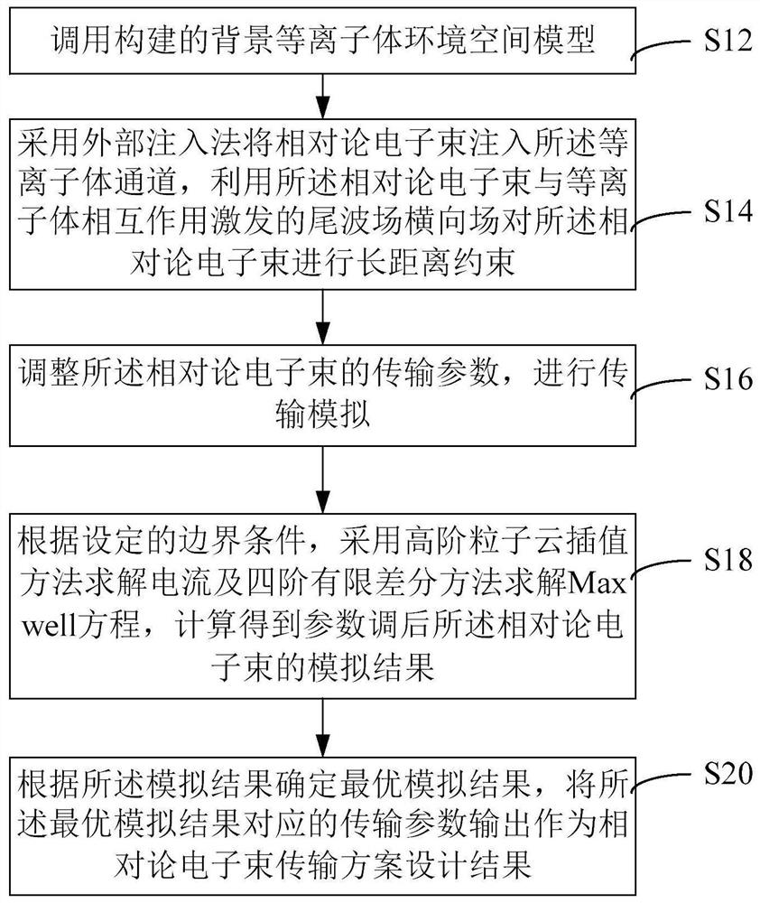
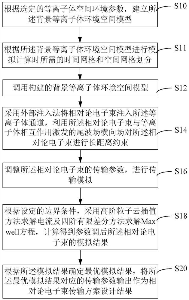
The invention relates to a relativistic electron beam transmission scheme design method and device, equipment and a medium. The method comprises the following steps: calling a background plasma environment space model; injecting the relativistic electron beam into a plasma channel by adopting an external injection method, and performing long-distance constraint on the relativistic electron beam by utilizing an excited tail wave field transverse field; adjusting transmission parameters of the relativistic electron beam, and performing transmission simulation; according to set boundary conditions, adopting a high-order particle cloud interpolation method to solve the current, adopting a fourth-order finite difference method to solve the Maxwell equation, and obtaining a simulation result of the relativistic electron beam after parameter adjustment through calculation; and determining an optimal simulation result according to the simulation result, and outputting a transmission parameter corresponding to the optimal simulation result as a relativistic electron beam transmission scheme design result, wherein the optimal simulation result is the simulation result when the beam spot of the relativistic electron beam is minimum, the energy collimation is optimal and the energy loss is minimum. The effect of efficient long-range stable transmission of relativistic electron beams is achieved.

Description

technical field [0001] The present application relates to the technical field of novel particle beam transmission, in particular to a design method, device, equipment and medium of a relativistic electron beam transmission scheme. Background technique [0002] In recent years, high-energy, highly collimated relativistic electron beams have been widely used in astronomy, inertial confinement fusion, radiology, and new detection technologies, and many potential application scenarios have certain requirements for long-distance transmission of relativistic electron beams. , such as high-energy electron beam transmission imaging technology and other new particle beam detection technologies. The research on the stability of long-distance transport of relativistic electron beams is of great significance to the study of electron beam transport capabilities and the exploration of new application fields of electron beams. [0003] The long-distance transmission of the relativistic el...

Claims


Application Information

Patent Timeline
Patent Type & Authority Applications(China)
IPC IPC(8): G06F30/23
CPCG06F30/23
Inventor 姚海波杨晓虎张国博马燕云王尚武徐涵
Owner NAT UNIV OF DEFENSE TECH
Learn More