
Automatic deslagging latex separator

An automatic slag discharge and separator technology, applied in centrifuges, centrifuges with rotating drums, etc., can solve the problems of low production efficiency and large manpower, improve production efficiency, prolong service time, and avoid feeding The effect of channel blockage

Pending Publication Date: 2021-11-09
CSSC NANJING LUZHOU MACHINE
View PDF0 Cites 2 Cited by
  • Summary
  • Abstract
  • Description
  • Claims
  • Application Information

AI Technical Summary

Problems solved by technology

This production efficiency is very low and requires a lot of manpower

Method used


Image

  • Automatic deslagging latex separator

Examples


Embodiment Construction

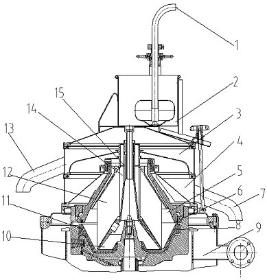
[0016] see figure 1 , the present embodiment provides a kind of automatic slag discharge latex separator, the top of the separator casing is equipped with a feed barrel 2, the pipeline of the feed barrel 2 is inserted into the center of the distributor 15 inside the drum, and the feed barrel 2 is provided with an inlet The feed pipe, the end of the feed pipe extending out of the barrel is connected to the natural fresh latex inlet 1, the disc 12 is sleeved on the rotating shaft of the drum, and the circumference of the disc 12 is provided with a heavy liquid channel 15, and the circumference of the distributor 15 The clear liquid channel 14 is set outward, and the upper cover 3 and the lower cover 4 are installed in the separation casing. The upper cover 3 is connected with the concentrated latex outlet 13 through the pipeline, and the lower cover 4 is connected with the latex outlet 7 through the pipeline, and the weight is relatively light. The concentrated natural rubber la...


PUM


Abstract

The invention relates to an automatic deslagging latex separator. The automatic deslagging latex separator is characterized in that a feeding barrel is arranged at the top of a separator shell, and a pipeline of the feeding barrel is inserted into the center of a distributor in a rotary drum; a feeding pipe is arranged in the feeding barrel, and the end, extending out of the barrel, of the feeding pipe is connected with a natural fresh latex inlet; a disc is connected to the distributor of the rotary drum in a sleeving mode, a heavy liquid channel is formed outside the circumference of the disc, and a clear liquid channel is arranged outside the circumference of the distributor; an upper cover and a lower cover are arranged in the separator shell, the upper cover is connected with a concentrated latex outlet through a pipeline, and the lower cover is connected with a skim latex outlet through a pipeline; light concentrated natural latex enters the light liquid channel, is thrown out of the rotary drum through centrifugal force, enters the upper cover and flows out through the concentrated latex outlet; heavy skim latex is thrown out of the rotary drum through centrifugal force, enters the lower cover and flows out through the skim latex outlet; heavies solid impurities are attached to the outermost side in the rotary drum and in a horn mouth through centrifugal force; and a solid impurity outlet is formed in the bottom of the separator shell. The separator can effectively prolong the separation service time, does not need to be frequently disassembled, assembled and cleaned, and improves the production efficiency.

Description

technical field [0001] The invention belongs to the technical field of separation equipment, and in particular relates to an automatic slag discharge latex separator. Background technique [0002] The natural rubber latex cut from the rubber tree has a rubber content (mass fraction) of 10-20%. Due to problems such as storage and transportation, it is necessary to concentrate the rubber content (mass fraction) in the latex to more than 60%. Latex concentration methods mainly include centrifugal method, creaming method, and evaporation method, but among various production methods of concentrated natural latex, centrifugal concentration method is the most, that is, disc centrifuge is used for concentration. [0003] Disc separator is a high-speed decanter centrifuge, which can quickly and effectively separate two kinds of liquid and solid mixture with high speed and strong centrifugal force. Because of its high-efficiency separation, it is widely used in ships, food, Pharmaceu...

Claims


Application Information

Patent Timeline
Patent Type & Authority Applications(China)
IPC IPC(8): B04B1/00B04B7/08B04B11/04B04B15/06B29B15/02
CPCB04B1/00B04B7/08B04B11/04B04B15/06B29B15/02
Inventor 蔡海闫媛媛胡敏肖海黄菊莲
Owner CSSC NANJING LUZHOU MACHINE
Learn More