
Efficient light alloy motor shell casting equipment

A technology for motor housing and casting equipment, which is applied to casting molding equipment, metal processing equipment, casting molds, etc. The effect of reducing temperature, avoiding vibration, and prolonging service life

Inactive Publication Date: 2021-11-09
彭鹏飞
View PDF0 Cites 1 Cited by
  • Summary
  • Abstract
  • Description
  • Claims
  • Application Information

AI Technical Summary

Problems solved by technology

[0005] Aiming at the deficiencies of the prior art, the present invention provides a high-efficiency light alloy motor shell casting equipment, which solves the problem that the temperature on the surface of the workpiece is not easy to lower during casting, and residues are easy to remain after casting to cause damage to the workpiece. Making it scrap reduces the usability of the equipment, and the energy is easy to cause waste, which reduces the processing efficiency of the equipment

Method used


Image

  • Efficient light alloy motor shell casting equipment
  • Efficient light alloy motor shell casting equipment
  • Efficient light alloy motor shell casting equipment

Examples


Embodiment 1

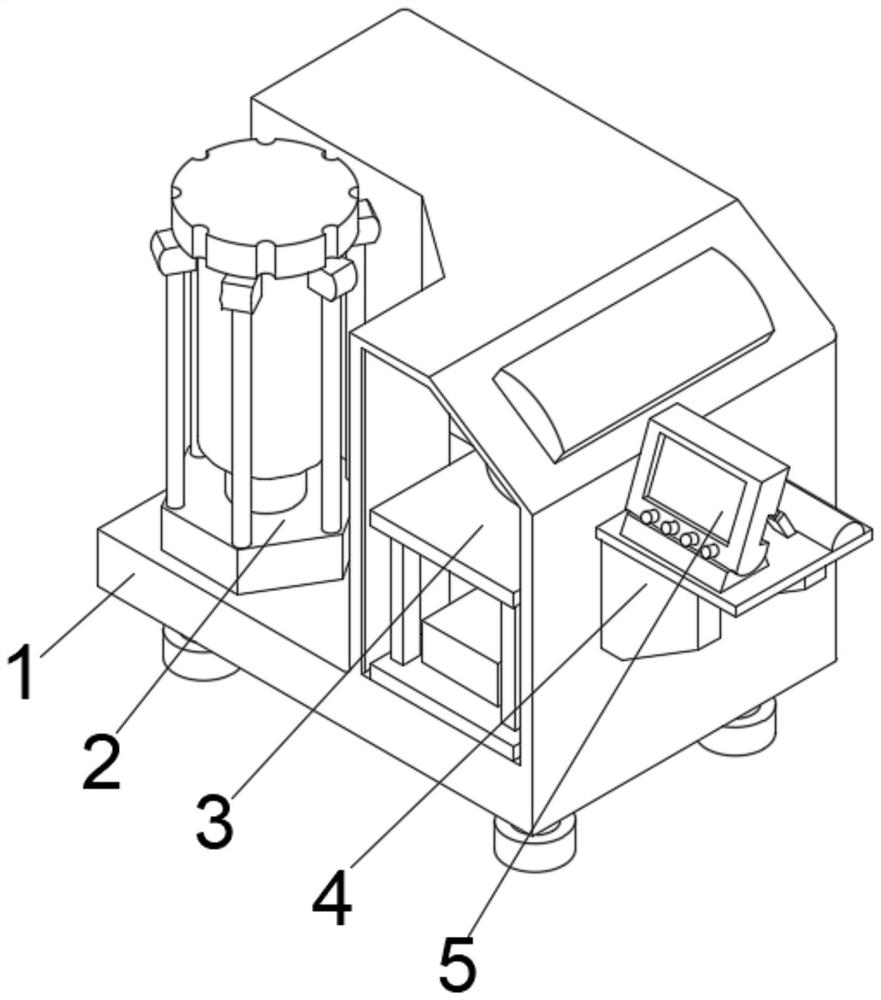
[0032] see Figure 1-2 , the present invention provides a technical solution: a high-efficiency light alloy motor shell casting equipment, including a casting main body 1, the middle part of the outer wall on the right side of the casting main body 1 is fixedly connected with a fixed bracket 4, and the top of the fixed bracket 4 is fixedly connected with a The control panel 5, the left side of the bottom of the casting body 1 is connected with a pressurizer 2, the bottom of the pressurizer 2 penetrates the casting body 1 and extends to the inside of the casting body 1, and the bottom of the inner cavity of the casting body 1 is fixedly connected with a casting device 3.

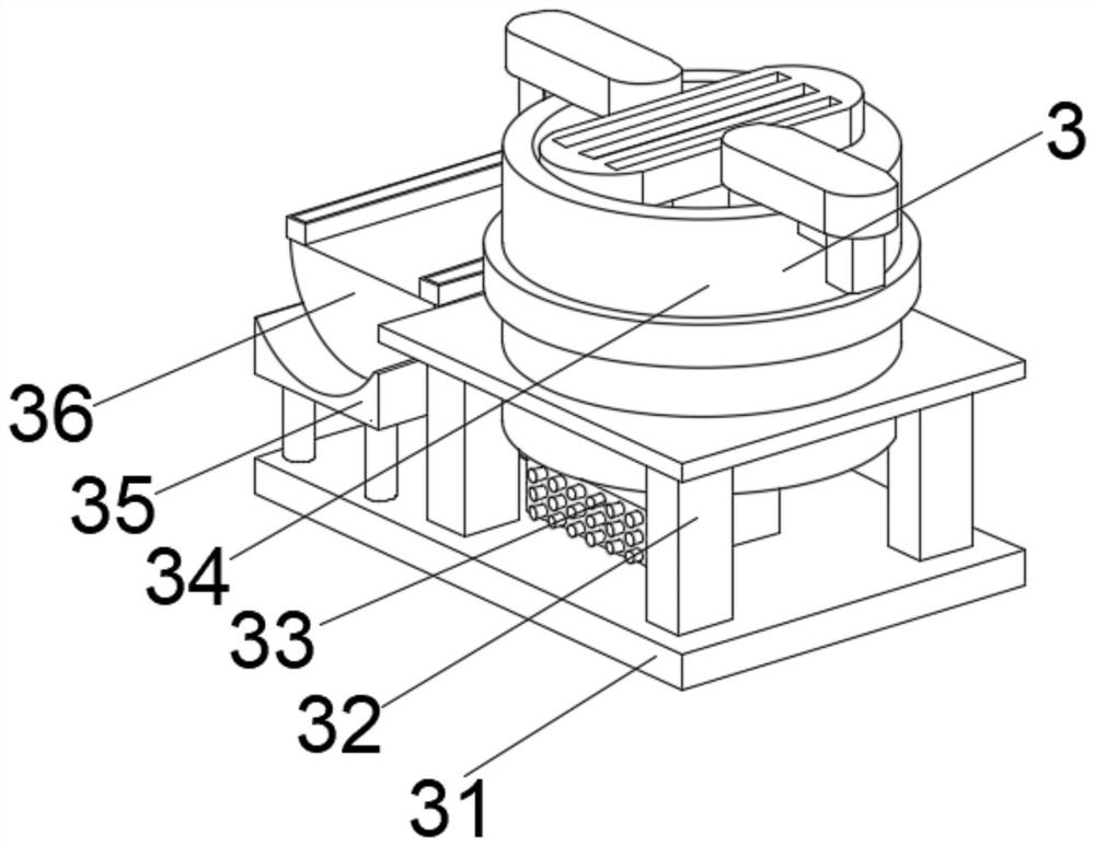
[0033] Among them, the casting device 3 includes a bottom board 31, the top left side of the bottom board 31 is fixedly connected with a connecting frame 35, the top middle position of the connecting frame 35 is fixedly connected with an adjustment mechanism 36, and the top right side of the bottom board 31 i...

Embodiment 2

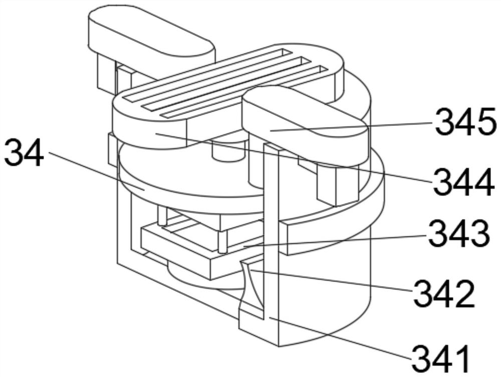
[0036] see Figure 1-4, on the basis of Embodiment 1, the present invention provides a technical solution: Component 1 of the casting mechanism 34 includes a housing 341, the middle position of the bottom of the inner cavity of the housing 341 is fixedly connected with a fastener 342, and the middle of the top of the fastener 342 The casting body 343 is fixedly connected, the top of the casting body 343 is provided with a spacer 344 , the top of the spacer 344 runs through the shell 341 , and the top of the shell 341 is located on both sides of the spacer 344 to be provided with a lifter 345 .

[0037] Wherein, the first component of the adjustment mechanism 36 includes an adjustment seat 361, the outer walls of both sides of the adjustment seat 361 are fixedly connected with adjustment columns 365, the middle position of the inner cavity bottom of the adjustment seat 361 is provided with a rotary transition 363, and the inner cavity bottom of the adjustment seat 361 Both side...

Embodiment 3

[0040] see Figure 1-6 , on the basis of Embodiment 1 and Embodiment 2, the present invention provides a technical solution: Component 2 of the casting mechanism 34 includes a protective cover d1, and a rotating part d4 is provided at the middle position of the inner cavity bottom of the protective cover d1, and the rotating part d4 Auxiliary leaves d5 are fixedly connected to the middle of the outer walls on both sides of the protective cover d1, a processing table d3 is fixedly connected to the middle of the inner walls of both sides of the protective cover d1, and a mold base d2 is fixedly connected to the middle of the top of the processing table d3.

[0041] Wherein, the second component of the adjustment mechanism 36 includes a driver t1, a transmitter t2 is arranged on one side of the outer wall of the driver t1, a positioning plate t3 is fixedly connected to the right outer wall of the transmitter t2, and a movable inner wall is provided on the right side of the positio...


PUM


Abstract

The invention discloses efficient light alloy motor shell casting equipment. The equipment comprises a casting main body, a fixing support is fixedly connected to the middle of the outer wall of the right side of the casting main body, a control panel is fixedly connected to the top of the fixing support, and a pressurizer is connected to the left side of the bottom of the casting main body. The bottom of an inner cavity of the casting main body is fixedly connected with a casting device. The invention relates to the technical field of motor shells. According to the efficient light alloy motor shell casting equipment, pressure is circulated in the equipment, meanwhile, an adjusting mechanism adjusts under the action of the pressure, casting can be assisted conveniently, the equipment has a movable maintenance space due to the arrangement of a fixed bracket, the problem that the equipment is not easy to replace after being damaged is solved, the internal residual scraps are effectively cleaned, the phenomenon that the surfaces of machined parts are damaged by the residues is further reduced, the internal temperature rise in the casting process can be reduced, and the safety of workers in the working process is effectively guaranteed.

Description

technical field [0001] The invention relates to the technical field of motor casings, in particular to a high-efficiency casting equipment for light alloy motor casings. Background technique [0002] A motor refers to an electromagnetic device that converts or transmits electrical energy according to the law of electromagnetic induction, or converts one form of electrical energy into another form of electrical energy. The motor converts electrical energy into mechanical energy (commonly known as a motor), and the generator is Convert mechanical energy into electrical energy, but the temperature on the surface of the workpiece is not easy to lower during casting, and residues are easy to remain after casting, causing damage to the workpiece, making it scrapped and reducing the usability of the equipment, and energy is easy to cause waste, reducing the equipment cost. processing efficiency. [0003] To sum up, it is not easy to reduce the surface temperature of the workpiece ...

Claims


Application Information

Patent Timeline
Patent Type & Authority Applications(China)
IPC IPC(8): B22C9/06B22C9/22B22D27/04B22D27/09
CPCB22C9/065B22C9/22B22D27/04B22D27/09
Inventor 彭鹏飞
Owner 彭鹏飞
Learn More