
Special-shaped curved surface part machining method and equipment based on multi-axis linkage milling machine center

A special-shaped curved surface and multi-axis linkage technology, which is applied in the direction of milling machine equipment, milling machine equipment details, metal processing equipment, etc., can solve the problems of reduced part processing efficiency, low part processing accuracy, and increased processing time, so as to improve processing accuracy and improve The effect of processing efficiency and improving the effect of use

Inactive Publication Date: 2021-11-09
深圳市鸿翔精密科技有限公司
View PDF8 Cites 0 Cited by
  • Summary
  • Abstract
  • Description
  • Claims
  • Application Information

AI Technical Summary

Problems solved by technology

[0002] In the process of CNC machining, the processed parts are divided into regular parts and special-shaped surface parts. When processing regular parts, you only need to install the set program for processing. When processing special-shaped surface parts, it is necessary to continuously plan the tool path. While satisfying high processing precision, processing efficiency cannot be improved
[0003] In the process of machining parts, the existing milling machine needs to change the tool frequently, which increases the processing time and reduces the processing efficiency of the part, and when the existing milling machine switches the tool, the switching accuracy is low, and it needs to be adjusted many times. The position of the tool after switching is adjusted, resulting in low machining accuracy of the parts, and the poor coordination of the existing milling machine with multi-axis linkage, which cannot make precise movements according to the machining path, which reduces the use effect of the multi-axis linkage milling machine

Method used


Image

  • Special-shaped curved surface part machining method and equipment based on multi-axis linkage milling machine center
  • Special-shaped curved surface part machining method and equipment based on multi-axis linkage milling machine center
  • Special-shaped curved surface part machining method and equipment based on multi-axis linkage milling machine center

Examples


Embodiment Construction

[0040]Next, the technical solutions in the embodiments of the present invention will be described in connection with the drawings of the embodiments of the present invention, and it is understood that the described embodiments are merely the embodiments of the present invention, not all of the embodiments. Based on the embodiments of the present invention, all other embodiments obtained by those of ordinary skill in the art are in the range of the present invention without making creative labor premise.

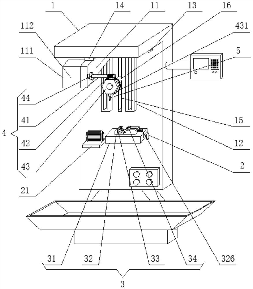
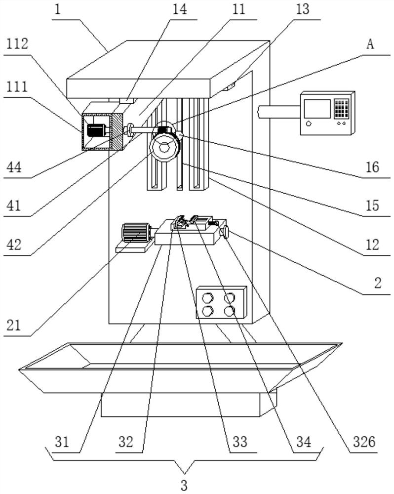
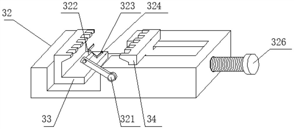
[0041] See Figure 1-9 The present invention provides a technical solution: a processing apparatus of a shaped curved mill based on a multi-axis linkage milling machine, including a milling machine body 1, a rotating shaft 2, a part clamping device 3, a processing device 4, and a milling cutter 5, a milling machine body 1 The side slide is mounted, the support plate 11 is mounted, the support plate 11 is used to mount the motor box 111, and the processing device 4 includes a worm ...


PUM


Abstract

The invention discloses a special-shaped curved surface part machining method and equipment based on a multi-axis linkage milling machine center, and belongs to the technical field of machining. The milling machine comprises a milling machine body, a rotating shaft, a part clamping device, a machining device and a milling cutter, wherein a supporting plate is slidably mounted on one side of the milling machine body; the machining device comprises a worm, a worm gear, a cutter mounting plate and an angle adjusting assembly; the worm is connected to an inner cavity of the angle adjusting assembly in a sleeved mode; the worm gear is clamped to a thread of the worm; the cutter mounting plate is fixedly mounted on one side of the worm gear; the angle adjusting assembly is fixedly mounted in an inner cavity of the supporting plate; the machining device is used for machining a special-shaped curved surface part; the worm is used for being matched with the motor to drive the worm gear to rotate; the cutter mounting plate drives a cutter to machine the special-shaped curved surface part under the action of the worm gear; and the angle adjusting assembly is used for limiting the rotation range of the worm.

Description

Technical field [0001] The present invention relates to the field of machine processing technology, in particular to a processing method and apparatus based on the multi-axis milling machines shaped surface parts of the center. Background technique [0002] NC machining process, machining parts and the divided parts shaped surface parts rules, the rules in the processing part, the installer simply set to be processed, the need to constantly when the tool path planning processing shaped surface parts, and in to meet the high precision, while not improve processing efficiency. [0003] Part of the conventional milling process, requires frequent tool replacement, so that processing time increases, reducing the efficiency of the processing parts, and a conventional milling machine when the tool is switched, the switching accuracy is low, the need for multiple the tool position adjusting switch, resulting in low machining accuracy, as well as a conventional multi-axis milling machine ...

Claims


Application Information

Patent Timeline
Patent Type & Authority Applications(China)
IPC IPC(8): B23C3/00B23C9/00B23Q3/157B23Q5/22B23Q15/013B23Q15/22
CPCB23C3/00B23C9/00B23Q3/157B23Q5/22B23Q15/013B23Q15/22
Inventor 何春斌范恩明
Owner 深圳市鸿翔精密科技有限公司
Learn More