
Correction method for B0 field pattern of magnetic resonance system

A correction method, magnetic resonance technology, applied in the direction of measuring magnetic variables, measuring devices, instruments, etc., can solve problems such as inaccurate calculation results, subsequent pixel calculation errors, lack of practical application value, etc., and achieve high calculation efficiency and excellent stability performance and accuracy, improving image quality

Pending Publication Date: 2021-11-09
NANJING GENERAL HOSPITAL NANJING MILLITARY COMMAND P L A
View PDF0 Cites 0 Cited by
  • Summary
  • Abstract
  • Description
  • Claims
  • Application Information

AI Technical Summary

Problems solved by technology

In the path-guided method, an evaluation function for the quality of the phase image is first selected. The full winding starts from a point in the 3D data, calculates the evaluation function along all directions, selects the direction with the highest evaluation value, and then performs a one-dimensional calculation along this direction. Phase dewrapping, the accuracy of this method depends on the selection of the quality function of the phase map, if the selection of the quality map is unreasonable, it will lead to inaccurate calculation results of the algorithm
However, the path-guided method lacks the global calculation of the phase map. When a certain path is wrong, it may cause calculation errors for subsequent pixels on the path, and it also lacks practical application value.

Method used


Image

  • Correction method for B0 field pattern of magnetic resonance system
  • Correction method for B0 field pattern of magnetic resonance system
  • Correction method for B0 field pattern of magnetic resonance system

Examples


Embodiment Construction

[0040] The present invention will be specifically introduced below in conjunction with the accompanying drawings and specific embodiments.

[0041] The B0 field map correction method of the present invention is suitable for performing B0 shimming on a magnetic resonance system, and specifically includes the following steps:

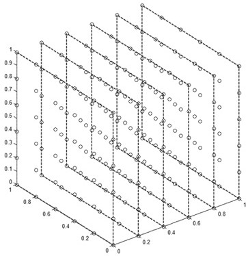
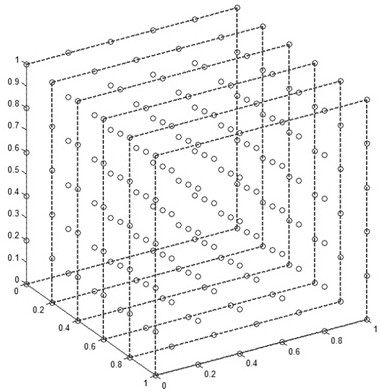
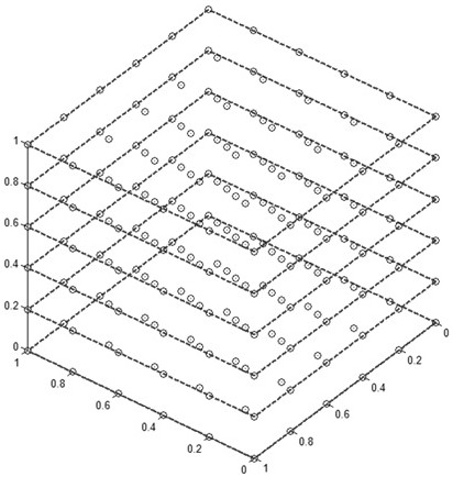
[0042] S1. Obtain the three-dimensional B0 field map of the magnetic resonance system, and divide it into several layers along each dimension.

[0043] Usually, we directly collect raw data to obtain a B0 field map. In this embodiment, a three-dimensional B0 field phase map M*M*M can be obtained by using a fast gradient echo sequence. Using fast gradient echo, two echoes are collected when the frequency encoding gradient is in the same direction, and the echo time is TE1 and TE2 respectively, and the two echoes are filled in K space 1 and K space 2 respectively, and reconstructed by Fourier Two complex images with different echo times were obtained for B...


PUM


Abstract

The invention provides a correction method for a B0 field pattern of a magnetic resonance system, and the method comprises the steps: firstly obtaining a three-dimensional B0 field pattern of the magnetic resonance system, and dividing the three-dimensional B0 field pattern into a plurality of layers along each dimension; performing 2D phase unwrapping layer by layer along at least two dimensions of the three-dimensional B0 field pattern to obtain a middle B0 field pattern; and finally, selecting one of the at least two dimensions as a reference direction, obtaining the phase difference between two adjacent layers in the B0 field pattern in the reference direction, and the phase difference meeting a global optimization rule. According to the method, 3D phase unrolling calculation is performed on the basis of a result obtained by performing 2D unrolling on each layer of a 3D phase one by one, and a global optimization rule is introduced, so that a shimming result has excellent stability and accuracy; moreover, the method disclosed by the invention is high in calculation efficiency, better meets the quick response requirement in practical application, and has a better clinical application prospect.

Description

technical field [0001] The invention relates to a method for correcting a B0 field map, in which a 3D phase unwinding method is applied; it belongs to the technical field of magnetic resonance imaging. Background technique [0002] In the magnetic resonance imaging system, the magnet itself can provide a relatively uniform static magnetic field B0 in a certain space, and the uniformity of the magnetic field is a key factor for the quality of the magnetic resonance image. However, due to the difference in tissue magnetic susceptibility, local magnetic field changes (ie, inhomogeneity) will occur at the junction, resulting in susceptibility artifacts, poor fat-pressing effects, and image distortion. Therefore, in order to improve the quality of the image, it is necessary to reduce the non-uniformity of the magnetic field (that is, shimming), so that it becomes a spatially continuous distribution, and the color does not jump to become a uniform image. In the prior art, a two-d...

Claims


Application Information

Patent Timeline
IPC IPC(8): G01R33/565
CPCG01R33/56563
Inventor 杨刚张龙江张志强卢光明许强戚荣丰张运明张其锐程晓青邱连丽
Owner NANJING GENERAL HOSPITAL NANJING MILLITARY COMMAND P L A
Learn More