Phased array radar wave control system based on FPGA and self-checking method

A phased array radar and wave control technology, applied in the field of radar, can solve problems such as high difficulty in research and development, insufficient computing and processing capabilities, complex large-scale phased array radar systems, etc., and achieve the effect of flexible design

Pending Publication Date: 2021-11-09
NANJING UNIV OF SCI & TECH
View PDF7 Cites 1 Cited by
  • Summary
  • Abstract
  • Description
  • Claims
  • Application Information

AI Technical Summary

Problems solved by technology

The large-scale phased array radar system is complex and difficult to develop, which makes the calculation and processing capabilities of the centralized wave control system with only one calculator insufficient.

Method used


Image

  • Phased array radar wave control system based on FPGA and self-checking method
  • Phased array radar wave control system based on FPGA and self-checking method
  • Phased array radar wave control system based on FPGA and self-checking method

Examples


Embodiment Construction

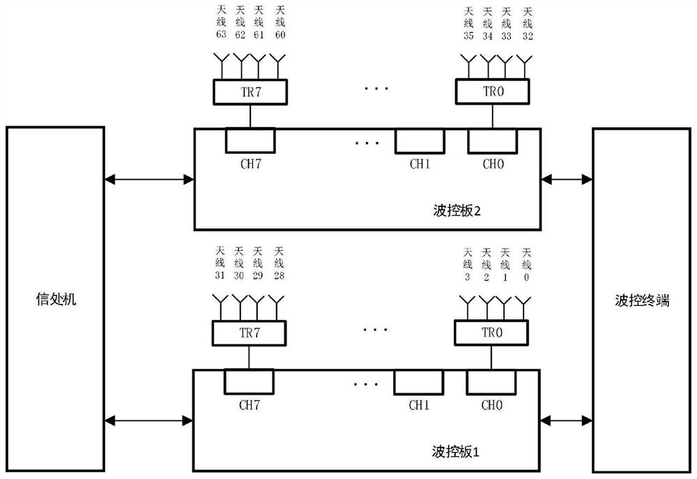
[0028] figure 1 It is a schematic diagram of hardware connection of an FPGA-based phased array radar wave control system in a radar system provided by an embodiment of the present invention. Such as figure 1 As shown, in the phased array radar system, the wave control system is an indispensable part. The wave control system mainly receives the instruction data from the signal processor under the control of the electronic computer, generates the required beam pointing code, and It is sent to the phase shifter in the T / R component to complete the directional control of the beam, which belongs to electrical scanning. Compared with traditional mechanical scanning, electronic scanning has huge advantages in speed and accuracy.

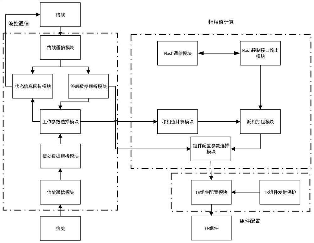
[0029] figure 2 It is a block diagram of software modules of the phased array radar wave control system according to an embodiment of the present invention. Such as figure 2 As shown, the wave control system is divided into three main modules: the wa...


PUM


Abstract

The invention provides a phased array radar wave control system based on an FPGA. The phased array radar wave control system comprises a wave control communication unit, a phase matching value calculation unit and a T / R assembly configuration unit. The wave control communication unit is used for completing communication of a medium wave control terminal and communication with a signal processing machine; the phase matching value calculation unit calculates the phase shift value of each channel according to the frequency point number and the wave position number transmitted by the communication instruction, and adds the phase shift value with the calibration value in the Flash to obtain the phase configuration parameter of the T / R assembly; and the T / R assembly configuration unit is used for configuring the phase configuration parameters of the T / R assembly to the TR assembly to ensure that the assembly works as required.

Description

technical field [0001] The invention relates to radar technology, in particular to an FPGA-based phased array radar wave control system and a self-inspection method. Background technique [0002] The wave control system is unique to the phased array radar. It replaces the role of the servo driver in the traditional mechanical scanning radar. Its main function is to calculate each wave according to the code of the beam pointing under the control of the data processor or mission computer. The control code required by the phase shifter on the antenna unit is transmitted, amplified, and sent to each phase shifter to control the receiving and transmitting phase of each antenna unit, so that the signal energy of each antenna unit of the phased array antenna can be specified in space Direction superimposed to form the antenna beam. [0003] The development trend of the wave control system is large-scale and distributed system, miniaturization and integration of single entity, high...

Claims


Application Information

Patent Timeline
Patent Type & Authority Applications(China)
IPC IPC(8): G01S7/28G01S7/40
CPCG01S7/28G01S7/4004
Inventor 王昊李一阳徐达龙王岩徐文文权双龙陶诗飞
Owner NANJING UNIV OF SCI & TECH
Why Eureka
Try Eureka