External current transformer and GIS
A current transformer, external technology, applied in the direction of inductor, transformer/inductor casing, transformer/reactor installation/support/suspension, etc., can solve the problem of large size, large size of current transformer, inner diameter of transformer coil Large and other problems, to achieve the effect of convenient installation and operation
- Summary
- Abstract
- Description
- Claims
- Application Information
AI Technical Summary
Problems solved by technology
Method used
Image

Examples
Embodiment 1
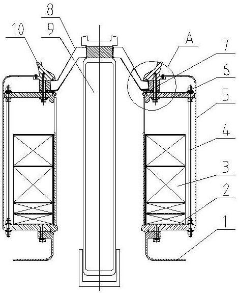
[0071] In this embodiment, compared with the prior art, the external current transformer in the GIS adopts the axial sealing method, cancels the valgus edge set on the top of the support cylinder, and reduces the size of the transformer shell so that it can be placed on the support The size of the transformer coil outside the cylinder is reduced accordingly, thereby reducing the overall size of the GIS, making the GIS compact and miniaturized, thereby reducing the layout space of the GIS.
[0072] Such as Figure 1 to Figure 6 As shown, the GIS in this embodiment includes an upper switching device, an external current transformer and a lower switching device arranged in sequence, and the switching devices on both sides respectively have electrical housings, wherein the upper switching device is specifically a disconnector, The lower switching device is a circuit breaker, the electrical housing of the isolating switch is the isolating switch housing 10, the electrical housing o...
specific Embodiment 2
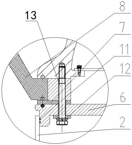
[0090] The main difference between it and Embodiment 1 is that in Embodiment 1, the transformer coils are arranged vertically and are directly set on the outer peripheral surface of the support cylinder, and the support screw supports and connects the top butt joint flange and the bottom support plate, and the bottom support plate is connected to the outer protective plate. The cover is hermetically fitted by a peripheral sealing ring. In this example, if Figure 7 As shown, the middle part of the support screw 4 is provided with a crimping rod 14 extending radially, and the end of the crimping rod 14 facing away from the support tube 22 is a nut sleeve, and the upper and lower sides of the nut sleeve are provided with fastening nuts and nut sleeves for fastening the top pressure. Contact and limit the crimping rod 14; the side pointing to the support cylinder 22 is a radial cylindrical rod. When the GIS is arranged horizontally, the transformer is arranged horizontally, and ...
specific Embodiment 3
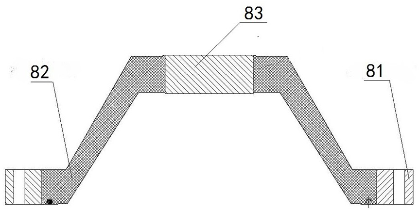
[0093] The main difference between it and Embodiment 1 is that in Embodiment 1, the center hole of the flange of the top butt flange is sealed and inserted into the support cylinder through the peripheral sealing ring. In this embodiment, an end face sealing ring may be provided on the inner end face of the limit rim of the central hole of the flange, and the top surface of the support cylinder is press-fitted with the end face sealing ring to realize the sealing fit of the end face.
PUM
 Abstract
Description
Claims
Application Information