Defrost system

A refrigeration device and circuit technology, applied in defrosting, household refrigeration devices, applications, etc., can solve problems such as reduced heat transfer efficiency

Active Publication Date: 2021-11-09
MAYEKAWA MFG CO LTD
View PDF7 Cites 1 Cited by
  • Summary
  • Abstract
  • Description
  • Claims
  • Application Information

AI Technical Summary

Problems solved by technology

[0004] During the operation of the refrigeration unit, frost adheres to the heat exchange tubes installed in the cooler, and the heat transfer efficiency decreases, so it is necessary to defrost (defrost)

Method used


Image

  • Defrost system
  • Defrost system
  • Defrost system

Examples


Embodiment Construction

[0024] refer to Figure 1 to Figure 6 Embodiments of the present invention will be described. In addition, in the description of the drawings, the same reference numerals are attached to the same elements, and overlapping descriptions are omitted. For convenience of explanation, the dimensional ratios in the drawings are exaggerated and may differ from actual ratios.

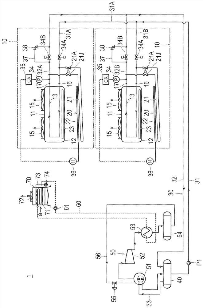
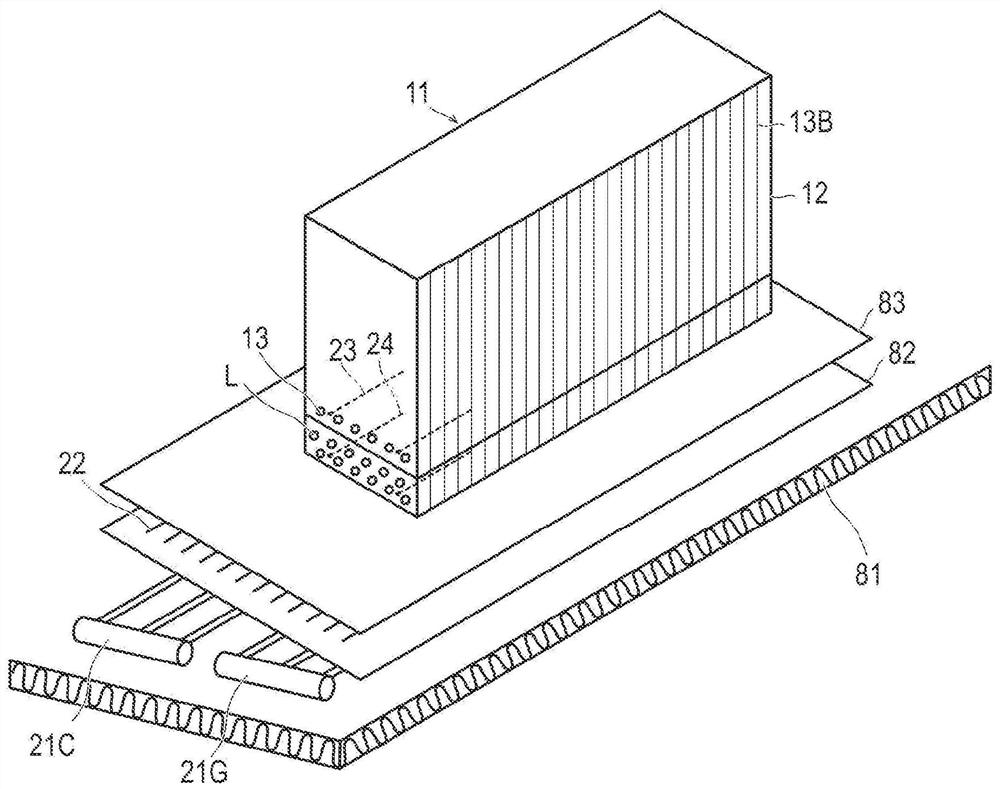
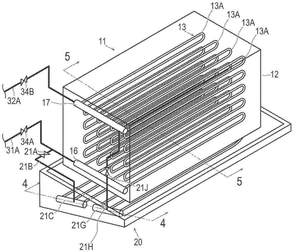
[0025] figure 1 It is an overall configuration diagram of the refrigeration device 1 at the time of the present embodiment. figure 2 It is a schematic perspective view of the cooler 11, the defrosting system 20, etc. which concern on this embodiment. image 3 It is a schematic diagram of cooler 11 and defrosting system 20 according to this embodiment. Figure 4 is along image 3 Cutaway view of line 4-4. Figure 5 is along image 3 Sectional view of line 5-5. Figure 6 It is a schematic diagram showing the thermosiphon defrosting circuit 21 according to this embodiment.

[0026] Such as figure 1 As sh...


PUM


Abstract

To provide a defrost system that can satisfactorily defrost without the introduction of a brine circuit and that can prevent the formation of icicles in a casing. A defrost system 20 comprises: a thermosiphon defrost circuit 21 provided so as to branch off from a circulation line 30 and to form a CO2 circulation path with a fin tube heat exchanger 13 containing a CO2 refrigerant which, during a defrosting operation, repeatedly undergoes a two-phase change between a gaseous state and re-liquefaction; an electromagnetic opening / closing valve 34A, 34B that closes during a defrosting operation to make the CO2 circulation path a closed circuit; and a first electric heater 22 disposed above the thermosiphon defrost circuit so as to be adjacent thereto. The defrost system 20 allows the CO2 refrigerant to naturally circulate around the closed circuit during the defrosting operation.

Description

technical field [0001] The present invention is suitable for making CO 2 A refrigeration device that cools the interior of the freezer by circulating a refrigerant through a cooler installed in the freezer, and relates to a defrosting system for removing frost adhering to a finned tube heat exchanger installed in the cooler . Background technique [0002] From the point of view of preventing the destruction of the ozone layer and preventing global warming, ammonia, which has high cooling performance but is toxic, is widely used as a primary refrigerant for indoor air conditioners and refrigerators used for freezing food. Odorless CO 2 Refrigeration unit as a secondary refrigerant. [0003] In such a refrigeration unit, a cascade condenser is used to connect the primary refrigerant circuit for ammonia refrigerant circulation and the CO 2 The secondary refrigerant circuit of the refrigerant cycle, ammonia refrigerant and CO in cascade condensers 2 Heat exchange between re...

Claims


Application Information

Patent Timeline
Patent Type & Authority Applications(China)
IPC IPC(8): F25B47/02F25D21/06
CPCF25B41/00F25B47/02F25D21/08F25B41/20F25B2309/06F25D17/02F25D21/002F25B25/005F25B15/04F25B41/40F25B2700/19F25B2600/2525F25B2400/01
Inventor 吉川朝郁忽那都志夫尼尔森·穆加贝茅岛大树大须贺延王
Owner MAYEKAWA MFG CO LTD
Why Eureka
Try Eureka